
General Assist Technical Reference
Zone Control Interface Wiring Loom / Harness
Applicable model: UTY-CDPXZC
Indoor unit PCB connection, replacement part identification and installation guidance
The UTY-CDPXZC Zone Control Interface requires a dedicated wiring loom to provide the connection between the indoor unit main PCB and the zone controller interface. The loom connects to terminal CN6 and must be secured correctly to maintain reliable communication.
1. Overview
When connecting the UTY-CDPXZC Zone Control Interface to a compatible indoor unit, the correct wiring loom or harness is required. This harness provides the electrical connection between the indoor unit main PCB and the zone control interface board.
The harness is supplied with new zone controller assemblies and is also available separately as a replacement or service part for existing installations.
2. Component description
| Connection point | Connection |
|---|---|
| Indoor unit | Main PCB terminal CN6 |
| Zone controller | UTY-CDPXZC Zone Control Interface board |
Important: Isolate power to the indoor unit before connecting or disconnecting the wiring loom. Ensure the connector is aligned correctly and fully seated. Do not force the plug into the PCB socket.
3. Part information
| Part name | Description | Part number | Application |
|---|---|---|---|
| Wiring loom / harness | Connects the indoor unit PCB terminal CN6 to the UTY-CDPXZC Zone Control Interface | 9709500019 | Replacement or service part for existing zone controller installations |
4. Installation procedure
| 1 | Isolate the indoor unit power supply before commencing work. |
| 2 | Route the zone-control-interface connecting cable from the indoor unit through the cable opening in the UTY-CDPXZC enclosure. |
| 3 | Connect the wiring loom securely to terminal CN6 on the indoor unit main PCB. |
| 4 | Connect the opposite end of the loom to the corresponding connector on the UTY-CDPXZC Zone Control Interface. |
| 5 | Use the supplied small cable ties to secure the loom and prevent movement or strain on the connectors. |
| 6 | Where an optional remote temperature sensor is installed, secure its cable together with the zone control harness using the same cable ties. |
| 7 | Check that all wiring is clear of sharp edges and moving components before refitting covers and restoring power. |
5. Wiring diagram
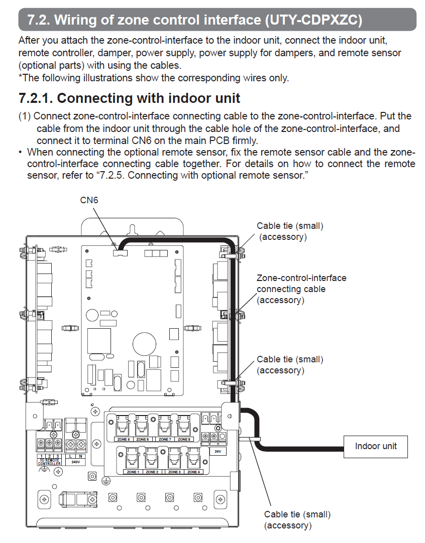
Connection summary: Indoor unit main PCB terminal CN6 → wiring loom part number 9709500019 → UTY-CDPXZC Zone Control Interface.