
GENERAL AIRSTAGE | VRF CONTROL SYSTEMS
UTY-APGXZ1 – System Controller
Centralised VRF Monitoring, Control and System Management
Applicable to supported AIRSTAGE VRF systems, including the V-IV R410A series.
The UTY-APGXZ1 is a PC-based centralised VRF System Controller designed to monitor and manage multiple AIRSTAGE VRF systems across small, medium and large buildings. It provides individual and group control, scheduling, fault monitoring, operating history and remote access.
1. System Controller Capacity
| Specification | UTY-APGXZ1 |
|---|---|
| Maximum VRF networks | 4 |
| Maximum indoor units / remote controller groups per network | 400 |
| Maximum indoor units / remote controller groups per System Controller | 1,600 |
| System Controllers per VRF network | 1 |
| Maximum client connections per server | 5 |
| Maximum host connections from client | 10 |
| History retention | 1 year for errors, operation and status history |
Different compatible VRF series can be connected to the separate supported VRF networks. The manufacturer specifies restrictions on which generations can coexist on an individual network. Confirm series compatibility before combining existing and new equipment.
2. How the System Controller Works
The UTY-APGXZ1 uses two separate software components:
| Software | Function |
|---|---|
| VRF Controller | Runs in the background on the site PC and communicates directly with the AIRSTAGE VRF networks through USB network interfaces. |
| VRF Explorer | Provides the graphical user interface used by building operators to control, monitor and manage the connected equipment. |
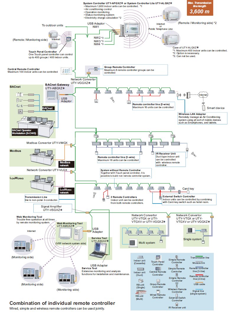
System Connection Architecture
| LOCAL OR REMOTE OPERATOR VRF Explorer software |
| ↓ LAN / Internet ↑ |
| SYSTEM CONTROLLER PC VRF Controller + WHITE-USB-KEY |
| ↓ USB ↑ |
| Echelon U10 USB Network Interface One interface per VRF network |
| ↓ VRF Transmission Network ↑ |
| AIRSTAGE VRF SYSTEM Outdoor units and indoor units |
Simplified functional architecture based on the manufacturer's system diagram. Refer to Chapter 5, page 05-16 for the complete network illustration.
Local and Remote Operation
The VRF Controller and VRF Explorer can run on the same computer or on separate computers connected through a network.
- On-site: VRF Controller communicates with the connected VRF networks. VRF Explorer can run on the same PC for local operation.
- Remote: VRF Explorer can connect to the site controller over a suitable LAN or Internet connection.
- Multiple buildings: Operators may connect to different sites from a central monitoring location, subject to the documented connection limits.
- Remote access restrictions: Certain functions, including equipment registration and input/output configuration, are not available from remote Explorer clients.
3. Required Hardware and Software
| Component | Requirement |
|---|---|
| UTY-APGXZ1 | System Controller software and WHITE-USB-KEY software protection device. |
| Computer | Locally supplied computer meeting the manufacturer's software requirements. |
| Echelon U10 | USB Network Interface, TP/FT-10 Channel, model 75010R. One required per VRF network. |
| USB connectivity | One USB port for the WHITE-USB-KEY and up to four USB ports for network interfaces. |
| Network | LAN or other supported network connectivity where remote monitoring is required. |
The on-site VRF Controller software only operates on a computer with the supplied WHITE-USB-KEY connected. Remote VRF Explorer clients do not require this key.
PC Requirements in the Technical Manual
| Operating systems listed | Windows 7 SP1, Windows 8.1 and Windows 10 (32-bit or 64-bit variants as specified) |
| Processor | Intel Core i3 2 GHz or higher |
| RAM | 2 GB minimum for Windows 7 32-bit; 4 GB for supported 64-bit and later configurations |
| Storage | 40 GB or more available space |
| Display | 1024 x 768 resolution or higher |
Current installation note: These are the legacy software requirements published in the V-IV technical manual. Before a new installation or PC replacement, confirm current Windows compatibility, installation software and licensing requirements with GENERAL Technical Support. Do not assume an operating system is supported simply because it is newer.
4. Available Control Functions
Individual Indoor Unit Control
- Start and stop operation.
- Select operating mode.
- Adjust temperature setpoint.
- Adjust supported fan speed and airflow direction.
- Enable supported economy functions.
- Set temperature upper and lower limits.
- Set remote controller operation restrictions.
- Reset filter notifications.
- Access supported human sensing functions.
Group and Building Control
- Create groups for sites, buildings and floors.
- Manage up to 1,600 groups.
- Organise groups across three hierarchical levels.
- Apply commands across selected groups of indoor units.
- Display indoor units using list, tree and graphical layouts.
- Use 2D site/floor and 3D building layouts.
- Save and reuse operation patterns.
5. Scheduling Functions
The UTY-APGXZ1 provides annual scheduling for building operation, allowing equipment to be managed according to the required occupancy patterns.
Supported schedule functions include:
- Week-of-year scheduling.
- Day-of-month scheduling.
- Day-of-week scheduling.
- Holiday and special-day schedules.
- Scheduled operation and associated control settings.
- Weekly low-noise scheduling for compatible outdoor units.
An office building can be configured to operate during normal business hours, follow a separate weekend schedule and apply special holiday periods without requiring occupants to manually operate every indoor unit.
6. Fault Monitoring and Operating History
The System Controller provides centralised fault reporting and system monitoring to assist technicians and building managers.
| Function | Description |
|---|---|
| Equipment status | Displays supported operating status and control information. |
| Fault notification | Displays system error notifications. |
| Audible alarms | Supports an audible fault alert. |
| Email notification | Can send error notification emails when correctly configured. |
| Error history | Stores up to one year of error history. |
| Operating history | Stores up to one year of operation and status history. |
| Special operation | Monitors supported defrost and oil recovery operation. |
Room temperature monitoring requires the applicable wired controller and indoor-unit temperature detection settings, as specified in the manual.
7. Optional Energy Management Functions
The UTY-APGXZ1 can be expanded using optional software.
| Option | Purpose |
|---|---|
| UTY-PEGXZ1 Energy Manager | Additional energy-saving functions, monitoring and electricity charge apportionment using electricity meter information. |
| UTY-PPGXP2 Prepaid Air Conditioning | Supports prepaid air conditioning management and associated charge collection. |
The manufacturer's specification identifies optional energy functions including indoor-unit lead/lag, outdoor-unit capacity limitation, peak-cut control and power consumption monitoring.
8. Installation and Commissioning Overview
The following is a general commissioning workflow. Use the dedicated UTY-APGXZ1 installation and software manuals for detailed installation, registration and configuration procedures.
- Confirm compatibility: Verify the VRF series, network configuration, indoor-unit count and required optional software.
- Prepare the PC: Verify that the selected computer and operating system are compatible with the System Controller software.
- Install network interfaces: Provide an Echelon U10 USB Network Interface for each VRF network being connected.
- Install software: Install the manufacturer's VRF Controller and VRF Explorer software.
- Connect the security key: Insert the required WHITE-USB-KEY into the site controller PC.
- Connect the VRF network: Follow the manufacturer's interface wiring and VRF transmission-network requirements.
- Register equipment: Configure the connected VRF networks and register the indoor and outdoor equipment using the approved software procedure.
- Configure site layout: Organise the equipment into buildings, floors and groups.
- Set operating controls: Configure required control permissions, schedules and fault notifications.
- Verify operation: Confirm that the equipment responds correctly to supported control commands and that faults and status are reported accurately.
- Configure remote access: Where required, establish authorised remote Explorer connections.
- Record configuration: Retain site configuration records, software versions, settings and backup information.
9. Troubleshooting
| Problem | Initial Checks |
|---|---|
| VRF Controller will not run | Verify software installation, computer compatibility and WHITE-USB-KEY connection. |
| No communication with VRF equipment | Check the U10 USB interface, drivers, USB connection, VRF transmission wiring and network status. |
| Indoor units not displayed | Check equipment registration, network assignments and physical network communication. |
| Remote Explorer cannot connect | Verify LAN connectivity, server operation, authorised client access and network configuration. |
| Schedules not operating as expected | Review schedules, holiday settings, equipment assignments and competing control commands. |
| Email error notifications not received | Check configured recipients, email delivery settings, network connectivity and the recorded error history. |
| Energy management functions missing | Confirm relevant optional software licensing, installation and system compatibility. |
10. Information Required for Technical Support
When escalating a System Controller issue, please provide:
- System Controller model: UTY-APGXZ1.
- Installed software version and operating system.
- Number of VRF networks and connected indoor units.
- Outdoor-unit models and system configuration.
- Details of the Echelon U10 USB interfaces.
- Confirmation that the WHITE-USB-KEY is connected and recognised.
- Description of the issue and when it first occurred.
- Screenshots of software errors, missing equipment or abnormal status.
- Any recent changes to the PC, operating system, network or controller software.
AIRSTAGE V-IV Design & Technical Manual – Oceania
Chapter 5: Control System
Section 2-1: System Controller (UTY-APGXZ1)
Pages 05-15 to 05-18
For detailed installation, network registration, software configuration and fault diagnosis, consult the dedicated UTY-APGXZ1 Installation and Operation Manuals.
GENERAL AIRSTAGE | Technical information for qualified installers, service technicians and building management personnel.