
GENERAL AIRSTAGE | VRF TECHNICAL SUPPORT
AIRSTAGE VRF – Modbus BMS Integration
Modbus Converter UTY-VMGX – Connection, Configuration and Troubleshooting
Applicable system: AIRSTAGE R410A VRF
The AIRSTAGE VRF system can be integrated with a Building Management System (BMS) using the optional UTY-VMGX Modbus Converter. This converter provides communication between the proprietary AIRSTAGE VRF transmission network and a third-party Modbus network, allowing compatible BMS equipment to monitor and control the air conditioning system.
1. Required Modbus Interface
| Model | Description | Application |
|---|---|---|
| UTY-VMGX | Modbus Converter for VRF | Connects the VRF transmission network to a Modbus BMS. |
| UTY-VMSX | Modbus Converter for Indoor Unit | Separate converter intended for individual indoor-unit integration, rather than system-wide VRF integration. |
Important: For integration of the VRF network, use the UTY-VMGX. The UTY-VMSX is a different interface and must not be treated as an equivalent replacement.
2. How the Modbus Connection Works
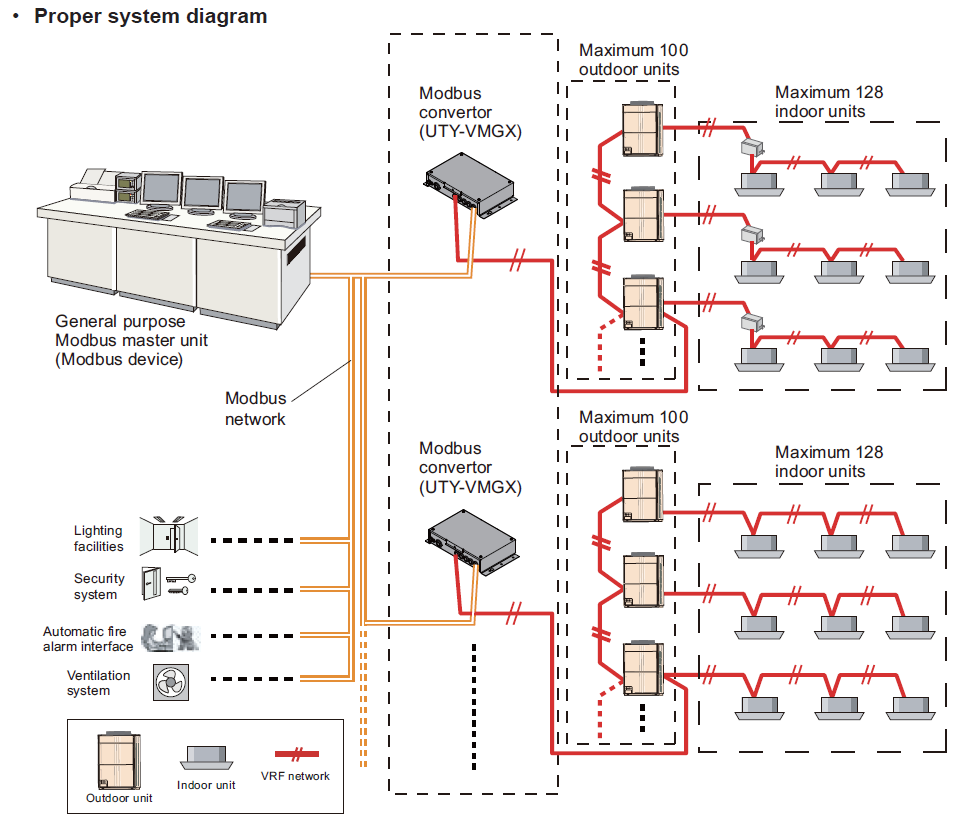
The UTY-VMGX operates as an interface between the external Modbus master and the VRF transmission network.
| BUILDING MANAGEMENT SYSTEM Modbus Master |
| ↓ Modbus Communication ↑ |
| UTY-VMGX Modbus Converter for VRF |
| ↓ AIRSTAGE VRF Transmission Network ↑ |
| AIRSTAGE VRF SYSTEM Outdoor Units + Indoor Units |
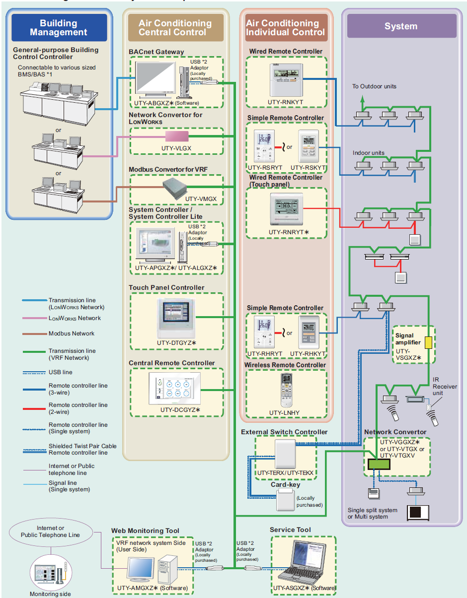
The converter receives commands from the Modbus network and transfers supported commands to the VRF equipment. It also makes supported equipment status information available for BMS monitoring.
3. System Connection Limits
| Parameter | Maximum |
|---|---|
| Indoor units per UTY-VMGX | 128 |
| Outdoor units per UTY-VMGX | 100 |
| Modbus converters per VRF network | 9 |
| Converters connected to one Modbus master without repeater | 31 |
| Converters connected to one Modbus master with repeater | 247 |
These are the published connection limits. The actual project design must also comply with the VRF network, wiring, addressing and device limitations.
4. Electrical and Communication Connections
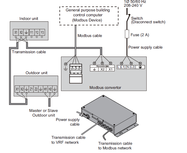
The UTY-VMGX has separate connections for the power supply, Modbus network and AIRSTAGE VRF transmission network.
| Connection | Purpose |
|---|---|
| Power supply | Single-phase 208–240 V AC, 50/60 Hz, through appropriate disconnect and 2 A fuse as illustrated in the manual. |
| Modbus network port | Connection to the third-party Modbus master network. |
| VRF network port | Connection to the AIRSTAGE VRF transmission network. |
| USB port | Connection to a computer for converter setup and registration using the supplied setup tool. |
Installation and wiring must be performed by appropriately qualified personnel. Isolate the supply before wiring. Do not connect mains voltage to communication terminals. Use the UTY-VMGX installation manual for terminal identification, cable specification, shielding, termination and wiring requirements.
Communication Switches
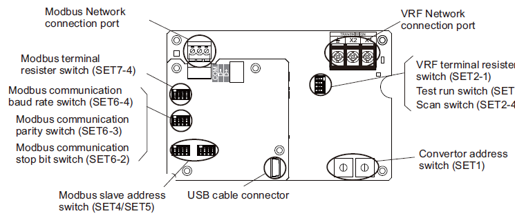
The manual identifies the following switches on the UTY-VMGX circuit board.
| Switch | Function |
|---|---|
| SET4 / SET5 | Modbus slave address |
| SET6-4 | Modbus baud rate |
| SET6-3 | Modbus parity |
| SET6-2 | Modbus stop bits |
| SET7-4 | Modbus termination resistor |
| SET1 | Converter address |
| SET2-1 | VRF termination resistor |
| SET2-3 | Test run |
| SET2-4 | Scan |
The project BMS settings and UTY-VMGX settings must match. Confirm the required baud rate, parity, stop bits and slave address using the converter installation manual and the BMS design documentation. The V-IV design manual identifies the relevant switches but does not provide a complete switch-position configuration table in this section.
5. Available BMS Control Functions
The following functions are identified in the manufacturer's control and monitoring tables. Availability depends on the system configuration and installed equipment.
Indoor Unit Control
| Function | Description |
|---|---|
| On / Off | Start and stop indoor-unit operation. |
| Operating mode | Select cooling, heating, auto, fan or dry. |
| Temperature setpoint | Set the required room temperature. |
| Airflow | Change supported airflow settings. |
| Temperature limits | Set upper and lower setpoint limits. |
| Remote controller restrictions | Restrict supported functions including operation, mode and setpoint adjustments. |
| Filter sign reset | Reset the filter notification. |
| Energy-saving mode | Set supported energy-saving functions. |
| Louvre control | Set supported vertical and horizontal louvre functions. |
| Test run | Issue the supported test-run command. |
System and Outdoor Unit Control
- System time-setting command.
- Emergency stop command.
- Outdoor unit low-noise setting.
- Outdoor unit capacity-limit setting.
6. Available BMS Monitoring Functions
The converter can provide supported monitoring information including:
- Indoor-unit On/Off status.
- Operating-mode status.
- Temperature setpoint status.
- Room temperature.
- Airflow and louvre status.
- Remote-controller restrictions.
- Indoor-unit error-code status.
- Defrost, oil recovery and pump-down status.
- Indoor-unit maintenance and emergency-stop status.
- Outdoor-unit low-noise status.
- Outdoor-unit capacity-limit status.
- Outdoor-unit error-code status.
- Converter communication settings, model and software version.
For exact registers, supported values, scaling, read/write permissions and Modbus function details, use the manufacturer's UTY-VMGX interface specification. The VRF design manual provides the available functions but is not a complete Modbus register map.
7. Registering Indoor and Outdoor Unit Addresses
The UTY-VMGX will not operate correctly unless the VRF network address-allocation information has been registered in the converter, or the installation meets the documented default-address conditions.
The manual identifies three registration methods.
Method 1 – Default Addresses
Where the documented default indoor and outdoor network addresses are used, initial address registration is not required.
The published default address ranges are:
- Indoor units: [00-00] to [00-63] and [01-00] to [01-63].
- Outdoor units: [00-00] to [00-03] and [01-00] to [01-03].
If the actual system addresses differ, use a supported registration method rather than assuming that the default address allocation applies.
Method 2 – Automatic Network Scan
- Confirm the VRF network is correctly installed and addressed.
- Turn on the converter's scan-setting switch (SET2-4).
- Confirm that the scan indication appears on the LED display.
- Wait for the converter to complete its scan and display the number of connected indoor units.
- Turn off the scan-setting switch.
- Confirm that the address-update indication is displayed.
- Restart the main power using the approved isolation and restart procedure.
- Confirm that address rewriting and synchronisation are completed.
If a scan error occurs, investigate the network and repeat the scan.
Method 3 – PC Registration
The supplied converter setup tool can also be used to register the network address information.
- Install the converter setup software on a compatible computer.
- Connect the computer to the UTY-VMGX using the supplied USB cable.
- Place the converter in USB mode.
- Configure the indoor and outdoor unit address information using the converter setup tool.
- Select the software registration function to write the information to the converter.
- Confirm successful registration before proceeding with BMS commissioning.
Note: The manual references a supplied DVD and legacy Windows software requirements. Confirm availability and compatibility of the current setup tool before attending site.
8. Commissioning Checklist
- Confirm that the installed interface is the correct UTY-VMGX converter.
- Check converter power supply and fuse.
- Verify the VRF network wiring and connection to the correct terminals.
- Check Modbus communication wiring and the relevant termination settings.
- Confirm the converter address and Modbus slave address are appropriate for the installation.
- Confirm baud rate, parity and stop-bit settings match the BMS.
- Confirm indoor and outdoor VRF address information is correctly registered.
- Verify that the expected number of indoor units is recognised.
- Test an approved individual indoor-unit On/Off command.
- Verify operating mode and setpoint command response.
- Confirm that indoor-unit status and room temperature are reported correctly.
- Verify alarm and fault reporting where practical.
- Confirm scheduled commands and local-controller restrictions behave as designed.
- Record all communication settings and commissioning results.
9. Important BMS Command Timing Restrictions
For periodic or scheduled commands, the manufacturer requires more than 10 minutes between the specified opposing operations. Commands must be coordinated across all indoor units within the same refrigerant system.
| First Command | Following Command | Interval |
|---|---|---|
| Start operation | Stop operation | More than 10 minutes |
| Release forced thermostat OFF | Set forced thermostat OFF | More than 10 minutes |
The manufacturer also specifies that forced thermostat OFF instructions must be issued by only one controlling device per refrigerant system. Multiple devices issuing these instructions may cause the system to respond incorrectly or malfunction.
10. Modbus Troubleshooting
| Problem | Recommended Checks |
|---|---|
| BMS cannot communicate with converter | Check converter power, Modbus cabling, termination, slave address, baud rate, parity and stop bits. |
| Converter communicates but no indoor units appear | Check VRF transmission wiring and network address registration. Carry out the documented scan or PC registration procedure. |
| Some indoor units missing | Verify indoor and outdoor addressing, number of discovered devices, system limits and VRF communication status. |
| Commands are not accepted | Verify register mapping, supported commands, controller restrictions, refrigerant-system status and other active control instructions. |
| Incorrect temperatures or status | Confirm the correct indoor-unit address and Modbus register, including the data interpretation and scaling defined in the interface specification. |
| Intermittent communication | Check cable installation, communication topology, termination, electrical interference and possible address conflicts. |
| Unexpected stopping or restarting | Review BMS schedules, competing controllers, command frequency and the manufacturer's 10-minute command restriction. |
11. Information to Provide to Technical Support
When escalating a Modbus communication issue, provide:
- VRF outdoor-unit models and refrigerant system addresses.
- Number of indoor and outdoor units installed.
- UTY-VMGX converter address and Modbus slave address.
- Baud rate, parity and stop-bit settings.
- Details of the BMS manufacturer and controller.
- Photographs of the converter PCB switch positions and wiring.
- Confirmation of the VRF address registration or scan result.
- Details of the failed command or monitoring point.
- Any displayed error codes or LED indications.
- Results of communication and control tests already completed.
AIRSTAGE V-IV Design & Technical Manual – Oceania
Chapter 5: Control System
Section 3-7: Modbus Converter for VRF (UTY-VMGX)
Manual pages: 05-139 to 05-145
Additional documentation required: UTY-VMGX Installation Manual, setup-tool Application Manual and Modbus Interface Specification.
GENERAL AIRSTAGE | Technical information for qualified installers, commissioning personnel and BMS integrators. Follow the equipment-specific installation documentation and applicable electrical regulations.