
General Assist Technical Reference
ARTC72 / ARTC90LATU Error Codes
How to reset faults, clear error history and identify what to check
Indoor: ARTC72LATU / ARTC90LATU | Outdoor: AOTA72LALT / AOTA90LALT
Use this article when an error is displayed on the wired remote controller or outdoor unit. Record the error code first, complete the checks below, then reset the system. If the fault condition remains, the error will return after restart.
Qualified service personnel only: Several checks require access to live electrical components, mains voltage, DC voltages, refrigerant pressures and inverter circuitry. Isolate power before checking wiring, connectors or component resistance.
1. How to reset an active error
- Record the error code before resetting. This is important because removing power may clear the active display.
- Turn the air conditioner off.
- Isolate power to the system. Leave power off long enough for the controls to shut down completely.
- Correct the cause of the fault using the checks in the table below.
- Restore power and operate the system.
- Confirm whether the error returns. If it reappears, continue troubleshooting rather than repeatedly resetting the unit.
Important: The service manual repeatedly specifies a power reset after correcting connector, wiring or thermistor faults. Some permanent protection faults will not clear until the underlying condition is corrected and power is reset.
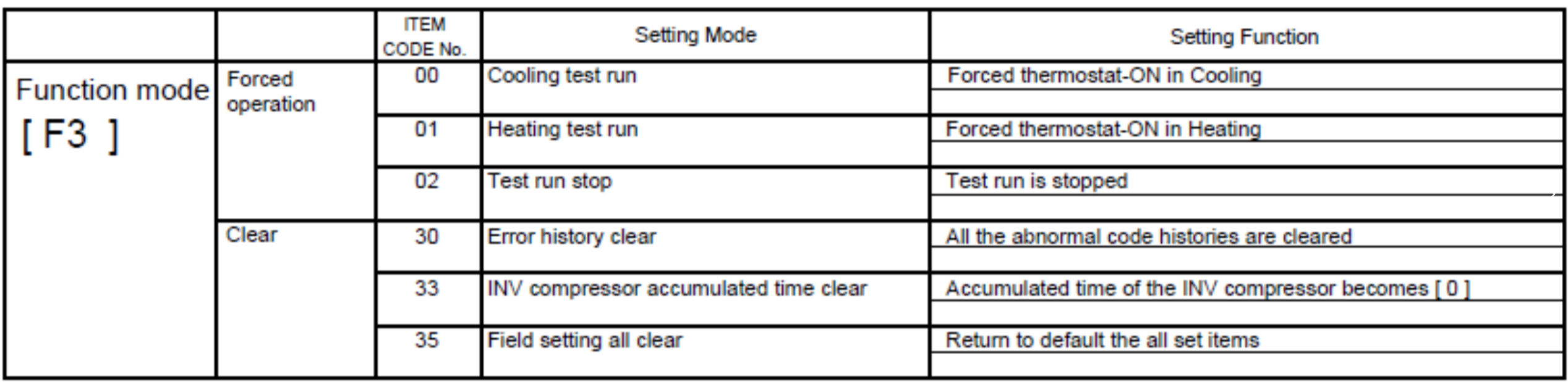
2. How to clear the outdoor unit error history
The outdoor PCB stores previous faults. Clearing the history does not repair an active fault; it only deletes the stored abnormal-code history.
| Step | Outdoor PCB procedure |
|---|---|
| 1 | With the unit stopped and powered, access the outdoor PCB controls. |
| 2 | Press MODE / EXIT (SW107). |
| 3 | Press SELECT (SW108) until F3 is displayed, then press ENTER (SW109). |
| 4 | Use SELECT to choose code 30 – Error history clear. |
| 5 | Hold ENTER to execute the selected F3 function. Confirm the display completes the command, then exit the function mode. |
Do not use “Field setting all clear” (F3 code 35) to clear fault history. Code 35 returns field settings to default. For error history only, use F3 code 30.
3. Wired remote controller error codes and what to check
| Code | Fault | What to check first |
|---|---|---|
| E00 | Wired remote controller error | Remote-controller cable and terminals; CN140 supply. Approx. DC12 V indicates controller fault; 0 V indicates indoor controller PCB fault. |
| E01 | Serial reverse transfer error | Indoor/outdoor interconnect wiring, loose connectors, earthing/noise, supply voltage and reverse serial signal. Manual specifies approx. AC70–130 V swing at outdoor terminals 1–3. |
| E02 / E13 | Serial forward transfer / indoor signal error | Indoor/outdoor wiring, connector condition, earthing/noise, supply voltage and forward serial signal. Manual specifies approx. AC70–130 V swing at outdoor terminals 2–3. |
| E04 | Indoor heat exchanger thermistor (middle) | Connector, open/short thermistor, resistance against temperature and DC5 V thermistor supply from indoor controller PCB. |
| E06 | Outdoor heat exchanger thermistor (outlet) | Sensor connector, damaged/open cable, thermistor resistance and DC5 V sensor supply from outdoor main PCB. |
| E0A | Outdoor temperature thermistor | Connector/cable, thermistor resistance and DC5 V sensor supply. |
| E0C | Outdoor discharge pipe thermistor | Connector/cable, thermistor resistance, sensor mounting and DC5 V sensor supply. |
| E0E | Heat sink thermistor (inverter) | Inverter PCB thermistor connector, open/short sensor, resistance and DC5 V supply. |
| E0F | Discharge temperature error | Service valves open, EEV/strainer, refrigerant shortage or leak, discharge thermistor, outdoor airflow, coil cleanliness and outdoor fan. Fault threshold is above 115°C. |
| E11 | Room temperature thermistor | Indoor thermistor connector/cable, open or short sensor, resistance and DC5 V controller PCB supply. |
| E12 | Indoor fan motor 1 lock | Fan rotates freely with power isolated, fan/shaft secure, no obstruction, motor not overheated, then power PCB/controller PCB. |
| E15 | Compressor thermistor | Sensor connector/cable, resistance, sensor mounting and DC5 V supply from main PCB. |
| E16 | Pressure switch / pressure sensor | Pressure-sensor connectors, 5 V PCB supply, sensor output voltage and pressure-switch continuity. Also confirm actual system pressures are reasonable. |
| E17 | IPM protection | Compressor/inverter connections, outdoor heat exchanger airflow, outdoor fan, compressor condition and inverter PCB. |
| E18 | Outdoor CT error | Reset once, check noise/earthing, wiring, Filter PCB CN501 signal, then Filter PCB or inverter PCB. |
| E19 | Inverter voltage protection | Supply interruptions/voltage drop, electrical noise, earthing, Filter PCB-to-inverter wiring, Filter PCB and inverter PCB. |
| E1A | Compressor location detection error | Compressor and inverter terminal connections, loose/open/miswired cables; if wiring is correct, inverter PCB. |
| E1b | Outdoor fan error | Fan turns freely, propeller/lock nut, ambient temperature around motor, Main Filter PCB fuse F602 and fan-motor supply voltages from main PCB. |
| E24 | Excessive high pressure protection – cooling | Connections, outdoor coil airflow/cleanliness, outdoor fan, outdoor heat exchanger thermistor, EEV and main PCB. |
| E2A | Power supply frequency detection error | Reset power, interconnect/control wiring, noise/earthing and power supply. Manual specifies AC198–264 V at L1-N, L2-N and L3-N. |
| E2b | Compressor temperature error | Service valves, EEV/strainer, refrigerant charge/leak, compressor thermistor, outdoor coil and outdoor fan. Fault threshold is 112°C or above. |
| E2C | 4-way valve / solenoid valve error | Connectors, indoor thermistors, solenoid coil resistance, 4-way valve operation and control voltage during heating. |
| E2E | Inverter communication error | Main PCB/inverter PCB wiring and connectors; check cement resistor; then main PCB/inverter PCB if fault remains. |
| E2F | Low pressure error | Low-pressure sensor connector, 5 V supply, refrigerant pressure/charge and leakage, then pressure sensor. Cooling fault condition is 0.12 MPa or less for 5 minutes after startup. |
| E34 | Indoor fan motor 2 lock | Fan rotation/obstruction, fan security, motor temperature, power PCB and controller PCB. |
| E37 | Indoor fan motor 1 driving circuit | Fan rotates freely, motor temperature and motor resistance from GND pin to remaining pins; replace fan motor if shorted. |
| E38 | Indoor fan motor 2 driving circuit | Fan rotates freely, motor temperature and motor resistance from GND pin to remaining pins; replace fan motor if shorted. |
4. Outdoor PCB error display
When an outdoor-unit error occurs, the ERROR lamp (LED102) flashes rapidly. The 7-segment display alternates between Err and the number of stored errors. Press ENTER (SW109) to display the error code, then use SELECT (SW108) to step through multiple errors.
| Outdoor code | Description |
|---|---|
| E.06 | Outdoor heat exchanger temperature sensor (outlet) |
| E.0A | Outdoor temperature sensor |
| E.0C | Outdoor discharge pipe temperature sensor |
| E.0E | Heat sink thermistor (inverter) |
| E.0F | Discharge temperature error |
| E.13 | Indoor signal / serial forward transfer error |
| E.15 | Compressor temperature sensor error |
| E.16 | Pressure switch / pressure sensor error |
| E.17 | IPM protection |
| E.19 | Inverter voltage protection |
| E.1A | Compressor location detection error |
| E.1b | Outdoor fan error |
| E.2b | Compressor temperature error |
| E.2E | Inverter communication error |
| E.2F | Low pressure error |
| E.98 | Pump down error |
| E.99 | Indoor unit error condition |
Good troubleshooting sequence: Record the code → inspect wiring/connectors → check airflow and mechanical condition → verify sensors/voltages/pressures where applicable → correct the cause → reset power → test operation → confirm the code does not return.