
AIRSTAGE | Technical Support Procedure
3 Wire Remote Signal Test
Testing the Y1, Y2 and Y3 wired remote-controller circuit
Electrical safety: This procedure must only be completed by a suitably qualified service technician. Isolate power before removing or reconnecting controller wiring. Take care not to short Y1, Y2 or Y3 during live voltage testing.
Purpose: Use this test to determine whether a three-wire wall controller, controller cable or indoor-unit control circuit is producing the correct supply and communication signal.
1. Terminal Identification
| Terminal | Typical wire colour | Function |
|---|---|---|
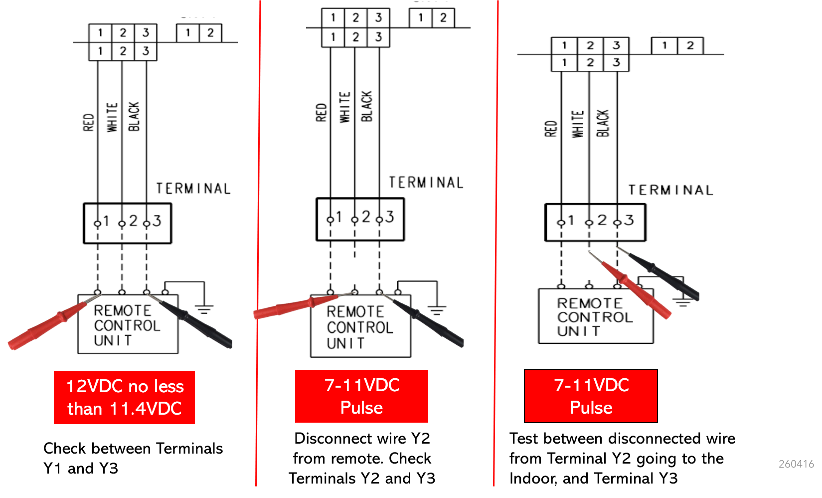
| Y1 | Red | Approximately 12 V DC supply |
| Y2 | White | Communication signal |
| Y3 | Black | Common / 0 V reference |
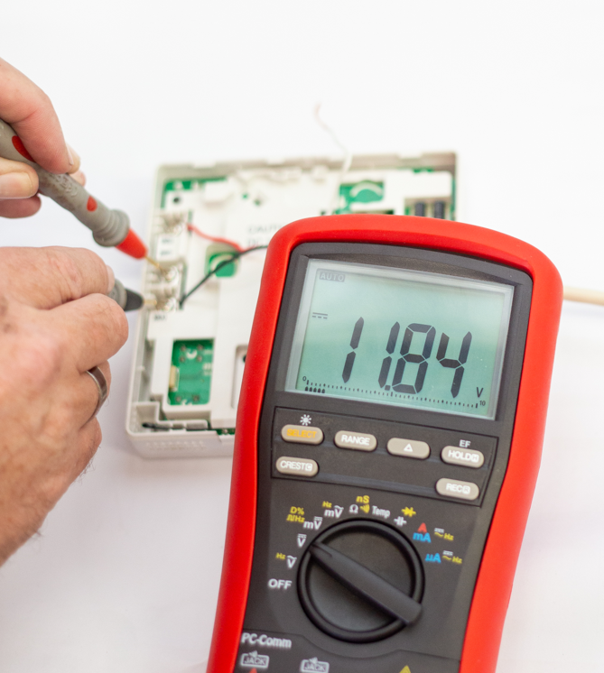
Meter setting: Set the multimeter to DC volts. Carry out all voltage measurements with reference to Y3 unless otherwise stated.
2. Test Procedure
Important: Isolate power before reconnecting Y2. Confirm all three conductors are secured in the correct terminals before restoring normal operation.
3. Result Interpretation
| Test result | Likely area to investigate |
|---|---|
| No voltage, or substantially less than 11.4 V DC, between Y1 and Y3 | Indoor-unit controller supply, indoor PCB, wiring connection, cable resistance or short circuit. |
| Correct Y1–Y3 supply, but no pulse between the wall controller's Y2 terminal and Y3 | Wall controller may be faulty or not transmitting correctly. |
| Correct pulse at the controller, but no pulse on the disconnected Y2 cable going to the indoor unit | Open circuit, incorrect termination, damaged cable, poor joint or high resistance in the controller wiring. |
| Pulse is present on both sides, but communication fault remains | Check polarity, terminal allocation, cable type, cable length, electrical interference, loose connections, controller compatibility and indoor PCB operation. |
4. Additional Checks
- Confirm Y1, Y2 and Y3 have not been crossed at either end.
- Inspect for loose terminals, damaged conductors or poor joins.
- Check the controller cable for continuity and insulation resistance with power isolated.
- Confirm the cable is not run alongside mains wiring where induced electrical noise may affect communication.
- Check that the installed wall controller is compatible with the indoor unit.
- After testing, reconnect all wiring and confirm normal controller operation and error-code status.
Technical summary: Y1 to Y3 provides the nominal 12 V DC supply. Y2 is the communication conductor and should display a pulsing voltage when tested against Y3. Separating the Y2 wire allows the technician to compare the wall-controller signal with the indoor-unit side of the circuit.