
General Assist Technical Reference
Test Run Procedure
AOTC72LALT / AOTC90LALT with ARTC72LATU / ARTC90LATU
Outdoor PCB test operation, pre-start checks and completion requirements
This procedure explains how to place the system into cooling or heating test operation from the outdoor unit PCB. The first test run should be completed in cooling mode.
Important: Configure test-run settings only while the outdoor unit is stopped and in standby. Do not operate the DIP switches or the PUMP DOWN button during this procedure.
1. Pre-test run checklist
| Check item | Done |
|---|---|
| Outdoor unit is securely installed | ☐ |
| Refrigerant joints, flares and brazed connections have been leak tested | ☐ |
| Gas pipe, liquid pipe and indoor drain extension are completely insulated | ☐ |
| Condensate drains correctly without leakage or restriction | ☐ |
| Power, control and interconnection cables are connected correctly | ☐ |
| Cable sizes and protection devices comply with specifications | ☐ |
| Earth connection is secure and correct | ☐ |
| Indoor and outdoor air inlets and outlets are unobstructed | ☐ |
| Specified refrigerant charge has been confirmed | ☐ |
| Gas and liquid service valves are fully open | ☐ |
| Crankcase heater has been energised for more than 6 hours | ☐ |
Do not proceed until every checklist item is confirmed. Rectify any installation or electrical issue first, then repeat the checks.
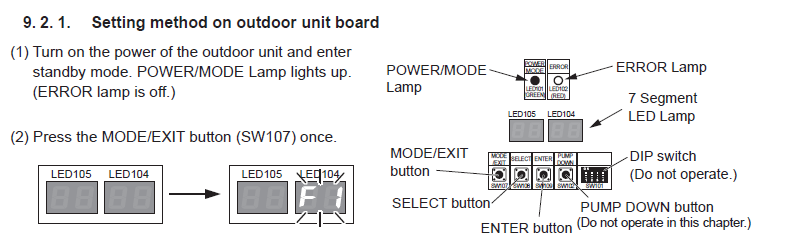
2. Outdoor PCB controls used
| Control | Reference | Use |
|---|---|---|
| MODE/EXIT | SW107 | Enter the outdoor-board menu or return to the previous level |
| SELECT | SW108 | Scroll through menu and operation codes |
| ENTER | SW109 | Confirm a selection; hold for more than 3 seconds to execute |
| LED104 / LED105 | 7-segment display | Shows menu and operation codes |
| POWER/MODE lamp | Green | Illuminated when the outdoor unit is powered and in standby |
| ERROR lamp | Red | Must be off before commencing the test-run setup |
The modes F1 and F9 are maintenance functions. Do not select them during normal test operation.
3. Starting test operation from the outdoor PCB
| 1 | Power the outdoor unit and confirm standby. The green POWER/MODE lamp must be on and the red ERROR lamp must be off. |
| 2 | Press MODE/EXIT once. LED104 will display F1. |
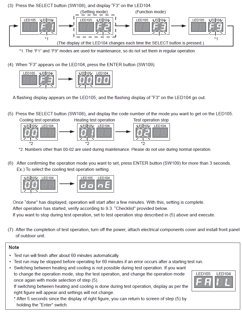
| 3 | Press SELECT until LED104 displays F3. The display cycles through F1, F2, F3 and F9. |
| 4 | Press ENTER once. LED105 will begin flashing and the F3 indication on LED104 will clear. |
| 5 | Press SELECT to choose the required test operation code. Use the table below. |
| 6 | Hold ENTER for more than 3 seconds. When done appears, the command has been accepted. Operation may take several minutes to begin. |
Test operation codes
| LED105 code | Operation | Instruction |
|---|---|---|
| 00 | Cooling test operation | Use for the first commissioning test run |
| 01 | Heating test operation | Use only after the cooling test has been completed |
| 02 | Stop test operation | Use to stop the test before the automatic 60-minute finish |
Codes other than 00, 01 and 02 are maintenance functions and must not be used during normal commissioning.
4. What happens during test operation
- The outdoor unit and connected indoor unit will operate continuously.
- Normal room-temperature control is disabled during test operation.
- Communication checks may delay startup by several minutes after “done” is displayed.
- Test operation will finish automatically after approximately 60 minutes.
- The system may stop earlier if a fault is detected.
- Heating and cooling cannot be changed directly while test operation is running.
If a knocking sound associated with liquid compression is heard from the compressor, stop the unit immediately. Energise the crankcase heater for sufficient time before attempting another test.
5. Stopping or changing the test mode
Stop test operation
- Return to the F3 test-operation menu.
- Select code 02 on LED105.
- Hold ENTER for more than 3 seconds.
- Confirm “done” is displayed and allow the unit to stop.
Change from cooling to heating, or heating to cooling
- Stop the current test using code 02.
- Return to the test-operation menu.
- Select code 00 for cooling or 01 for heating.
- Hold ENTER for more than 3 seconds to start the new test.
Attempting to change directly between heating and cooling during test operation may display a refusal indication and the mode will not change.
6. Test-run observations to record
| Observation | Recorded |
|---|---|
| Supply voltage and phase balance | |
| Compressor running current | |
| Suction and discharge pressures | |
| Return-air and supply-air temperatures | |
| Indoor and outdoor fan operation | |
| Drainage and condensate performance | |
| Abnormal vibration, noise or refrigerant movement | |
| Outdoor LED or controller fault indications |
7. Completion
- Allow the test to finish automatically or stop it using code 02.
- Turn off power before refitting electrical covers.
- Refit the outdoor electrical-components cover and front panel.
- Restore power and confirm normal controller operation.
- Record all test results, refrigerant charge and commissioning observations.
This article is based on the supplied installation-manual test-run instructions for AOTC72LALT / AOTC90LALT outdoor units matched with ARTC72LATU / ARTC90LATU indoor units. Confirm the exact model and current installation manual before commissioning.