
General Assist Technical Reference
ARTH Ducted Controller Wiring
Changing the indoor unit from 2-wire to 3-wire control for anywAiR ducted systems
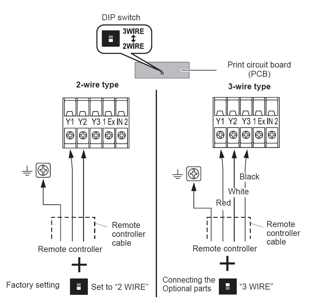
Applicable to ARTH ducted indoor units fitted with selectable 2-wire / 3-wire controller input
ARTH ducted indoor units are factory configured for a 2-wire wired controller. The anywAiR ducted controller uses a 3-wire controller connection, so the indoor PCB selector switch must be moved to the 3 WIRE position before commissioning.
Common symptom: If the unit remains set to 2-wire while an anywAiR 3-wire controller is connected, the controller may fail to communicate or display FG1.
1. Controller type selection
| Controller type | Indoor terminals used | Selector position | Typical application |
|---|---|---|---|
| 2-wire controller | Y1 and Y2 | 2 WIRE | Standard 2-wire wired remote controller |
| 3-wire controller | Y1, Y2 and Y3 | 3 WIRE | anywAiR ducted controller and other compatible 3-wire controls |
Factory setting: The indoor unit is supplied with the selector switch set to 2 WIRE. This must be changed manually when installing an anywAiR ducted controller.
2. Changing the indoor unit to 3-wire control
| 1 | Isolate power. Turn off the indoor and outdoor unit power supply before opening the indoor electrical/control box. |
| 2 | Remove the control-box cover. Loosen the cover screws and access the indoor PCB and controller terminal block. |
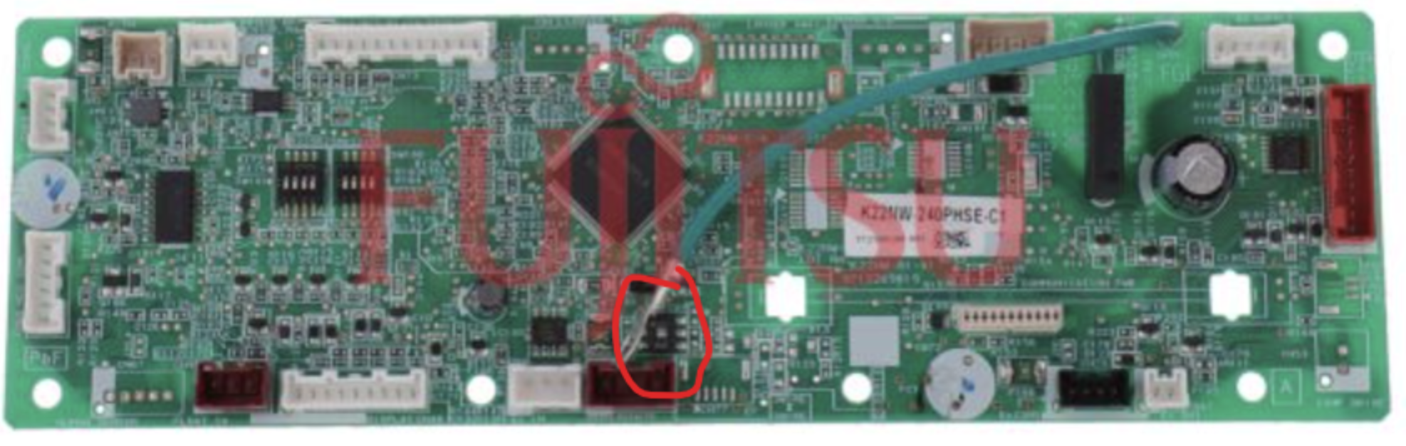
| 3 | Locate the 2 WIRE / 3 WIRE selector. The selector is mounted on the indoor printed circuit board near the controller terminals. |
| 4 | Move the selector to 3 WIRE. Confirm the switch is fully seated in the 3 WIRE position. |
| 5 | Connect the anywAiR controller to Y1, Y2 and Y3. Maintain the required wire order and polarity shown in the anywAiR installation instructions. |
| 6 | Secure and separate the wiring. Keep controller wiring clear of power and indoor/outdoor connection cables. |
| 7 | Refit covers and restore power. Allow the controller to initialise and confirm normal communication. |
3. Wiring requirements
| Connection | Requirement |
|---|---|
| 2-wire control | Use Y1 and Y2 only, with the PCB selector set to 2 WIRE. |
| 3-wire anywAiR control | Use Y1, Y2 and Y3, with the PCB selector set to 3 WIRE. |
| Controller cable | Use the cable type and maximum length specified in the anywAiR installation manual. |
| Cable routing | Keep remote-controller wiring separated from power wiring and the indoor/outdoor connection cable. |
| Earth | Earth the controller where the controller or cable includes a required earth conductor. |
Do not connect the controller to terminals 1, 2 and 3 used for the indoor/outdoor connection cable. The anywAiR controller must connect only to the dedicated Y1, Y2 and Y3 controller terminals.
4. FG1 or controller communication fault
Where an anywAiR ducted controller displays FG1 during first-time setup on an ARTH indoor unit, the first check should be the indoor PCB 2-wire / 3-wire selector.
| Check | Required condition |
|---|---|
| PCB selector | Set to 3 WIRE |
| Controller terminals | Connected to Y1, Y2 and Y3 |
| Wire sequence | Correct at both indoor unit and controller |
| Cable continuity | No open circuits, shorts or reversed conductors |
| Power cycle | Indoor unit isolated and restarted after changing the switch |
| Controller compatibility | Correct anywAiR ducted controller and interface for the indoor model |
After moving the selector, fully isolate power before restarting the system. The controller may not recognise the revised wiring configuration until the indoor PCB has been power cycled.
Field example
In the example , the anywAiR ducted controller was not communicating because the indoor unit remained in its factory 2-wire configuration which generated an FG1 error. Moving the selector to 3-wire allowed the controller to operate through Y1, Y2 and Y3.
5. Commissioning checklist
| Check | Done |
|---|---|
| Complete indoor-unit model confirmed as ARTH range | ☐ |
| anywAiR controller confirmed as 3-wire type | ☐ |
| Indoor PCB selector moved to 3 WIRE | ☐ |
| Y1, Y2 and Y3 wiring confirmed | ☐ |
| Controller cable separated from power wiring | ☐ |
| Indoor unit power cycled after switch change | ☐ |
| Controller starts without FG1 | ☐ |
| Mode, setpoint, fan and zone operation tested | ☐ |
Best practice: Check and set the controller type before fitting the control-box cover. This avoids unnecessary fault finding after the anywAiR system is powered for the first time.
This article is based on the supplied ARTH indoor-unit wiring diagram and field-support example. Always confirm the exact indoor model, anywAiR controller version and current installation manual before completing the installation.