
General Assist Technical Reference
anywAiR iO to RTPU
Installation, wiring, SMT-770 configuration and communication checks
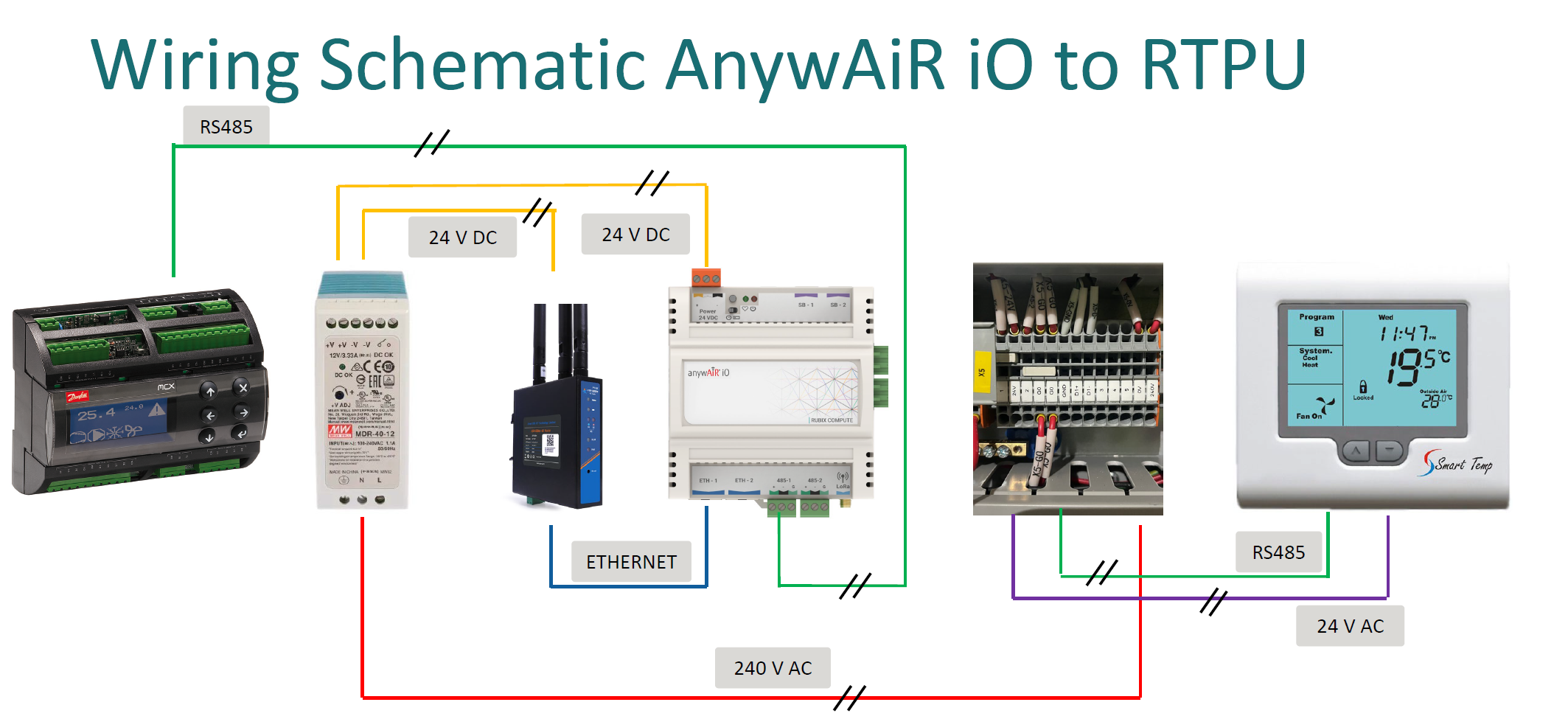
For General / AIRSTAGE rooftop package-unit applications using Rubix Compute and Smart Temp SMT-770
The anywAiR iO solution interfaces the RTPU Danfoss controller with the Smart Temp SMT-770 through the Rubix Compute gateway. The system uses separate power supplies and RS485/Modbus communication paths that must be wired and configured correctly.
Qualified personnel only: This installation includes 240 V AC, 24 V AC, 24 V DC and RS485 wiring. Isolate all supplies before installation and confirm polarity before energising equipment.
1. System overview
| Component | Power | Communication |
|---|---|---|
| Danfoss RTPU controller | Existing RTPU supply | RS485 to Rubix Compute |
| Rubix Compute anywAiR iO | 24 V DC | 485-1 to RTPU; Ethernet to optional modem/router |
| Smart Temp SMT-770 | 24 V AC | RS485 to RTPU X5 D1+ / D1- |
| 24 V DC power supply | 240 V AC input | Supplies Rubix and optional modem |
2. RTPU terminal X5 wiring
| Terminal | Function | Connection |
|---|---|---|
| 24V | 24 V AC active | SMT-770 Power 24 |
| 2 | 24 V AC neutral/common | SMT-770 Power 24C |
| D1+ | RS485 / Modbus positive | SMT-770 COMS A |
| D1- | RS485 / Modbus negative | SMT-770 COMS B |
| 0V / 240V | 240 V AC supply | 24 V DC power-supply input |
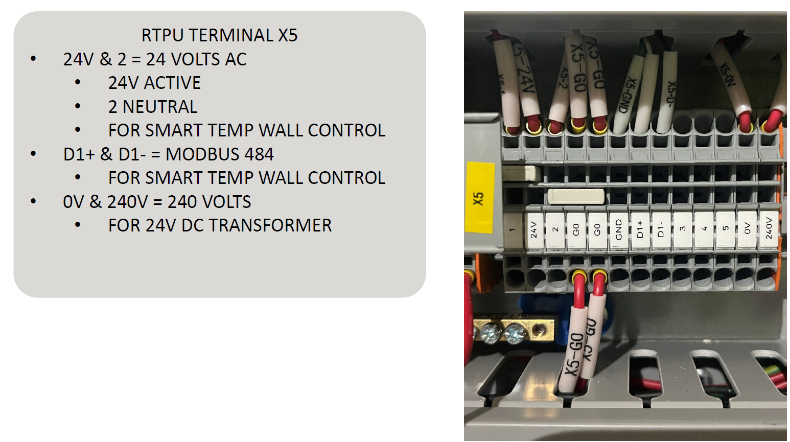
Confirm all RTPU X5 terminal labels against the actual unit wiring diagram before connection. Do not assume terminal position from wire colour alone.
3. Rubix Compute wiring
| Rubix terminal | Connection |
|---|---|
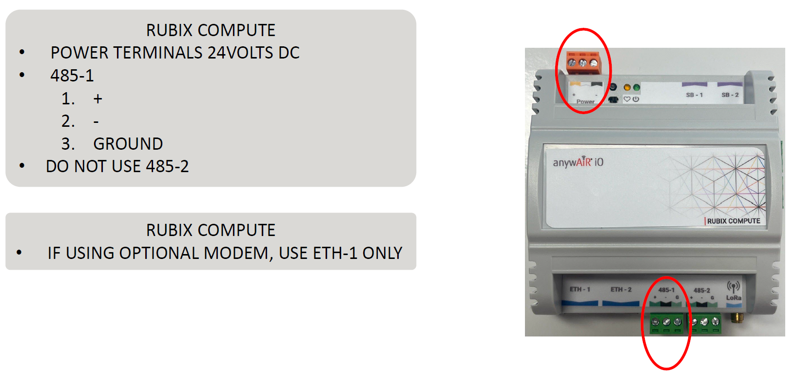
| Power + | 24 V DC positive |
| Power - | 24 V DC negative |
| 485-1 terminal 1 | RS485 positive (+) |
| 485-1 terminal 2 | RS485 negative (-) |
| 485-1 terminal 3 | Ground / reference |
| 485-2 | Do not use |
| ETH-1 | Use for optional modem/router connection |
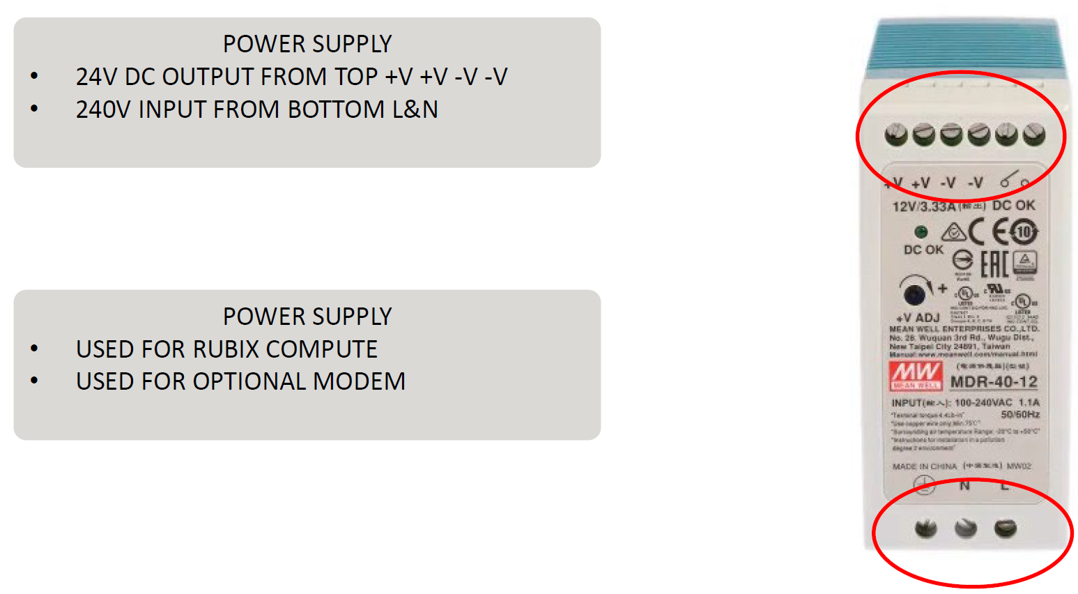
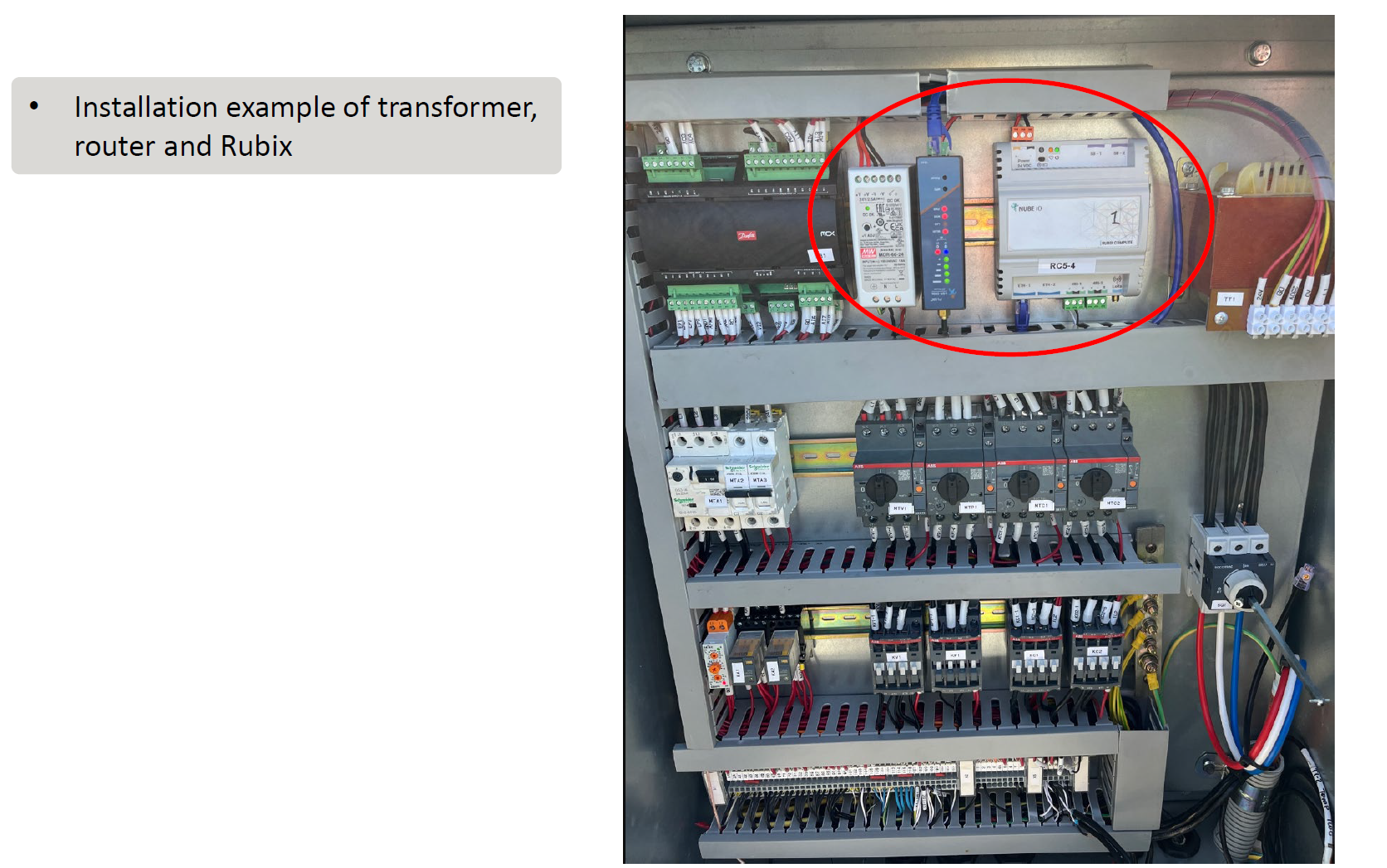
The 24 V DC power supply feeds both the Rubix Compute and the optional modem. The power supply receives 240 V AC at L and N and provides 24 V DC from the +V and -V output terminals.
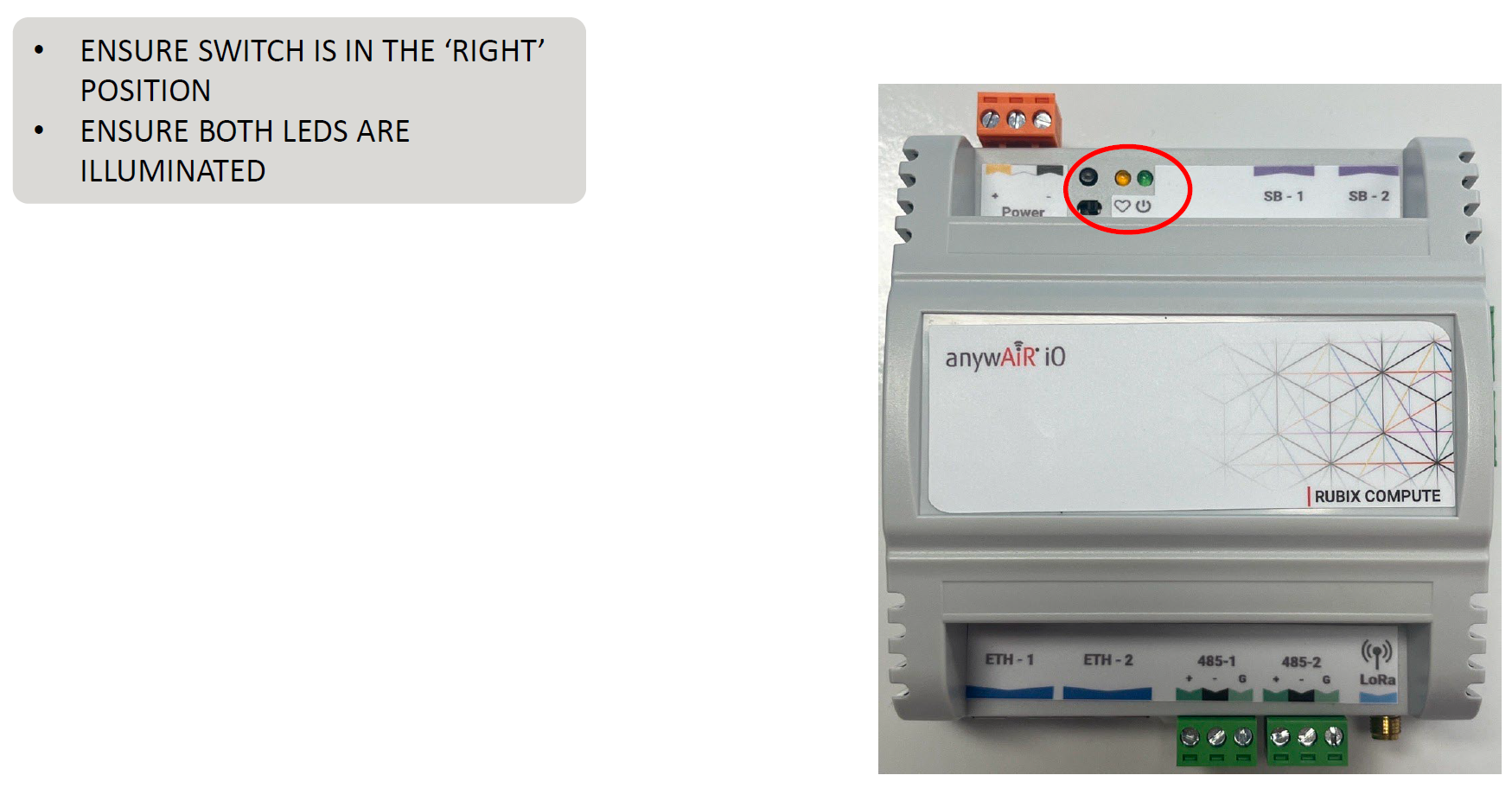
Rubix status check
- Confirm the local slide switch is in the right-hand position.
- Confirm both indicated status LEDs are illuminated.
- Confirm 24 V DC polarity before connecting the Rubix.
- Confirm RS485 polarity and grounding.
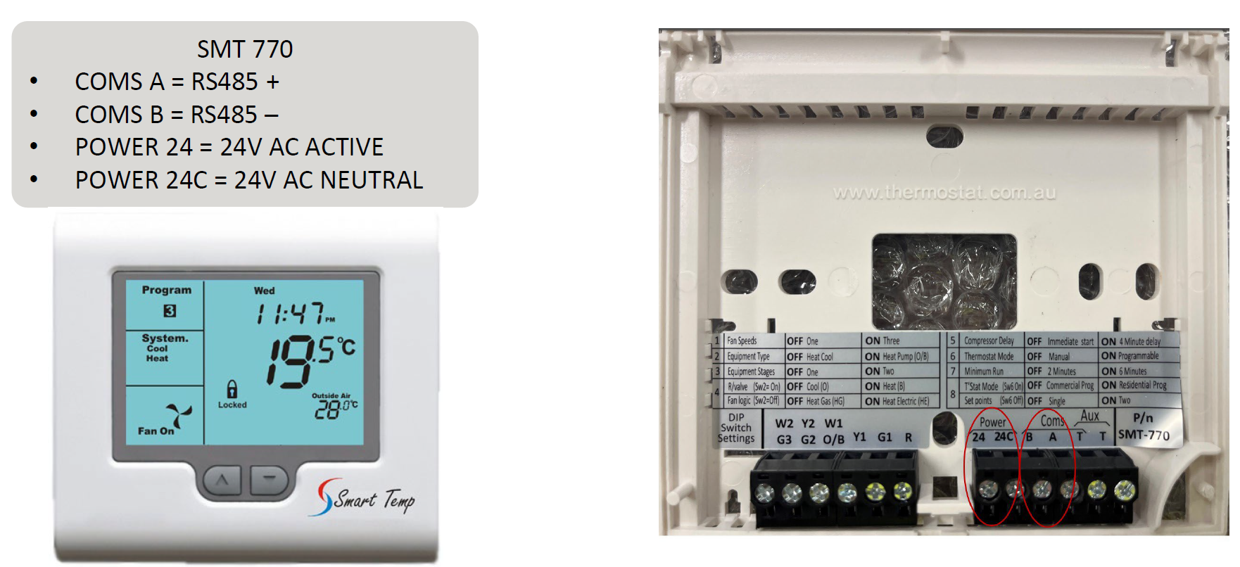
4. SMT-770 wiring and configuration
| SMT-770 terminal | Connection |
|---|---|
| COMS A | RS485 positive / RTPU D1+ |
| COMS B | RS485 negative / RTPU D1- |
| Power 24 | 24 V AC active |
| Power 24C | 24 V AC common / neutral |
SMT-770 DIP switches
| Switch | Required position | Purpose |
|---|---|---|
| 1 | OFF | Factory position |
| 2 | ON | Factory position |
| 3 | ON | Factory position |
| 4 | ON | Factory position |
| 5 | ON | Factory position |
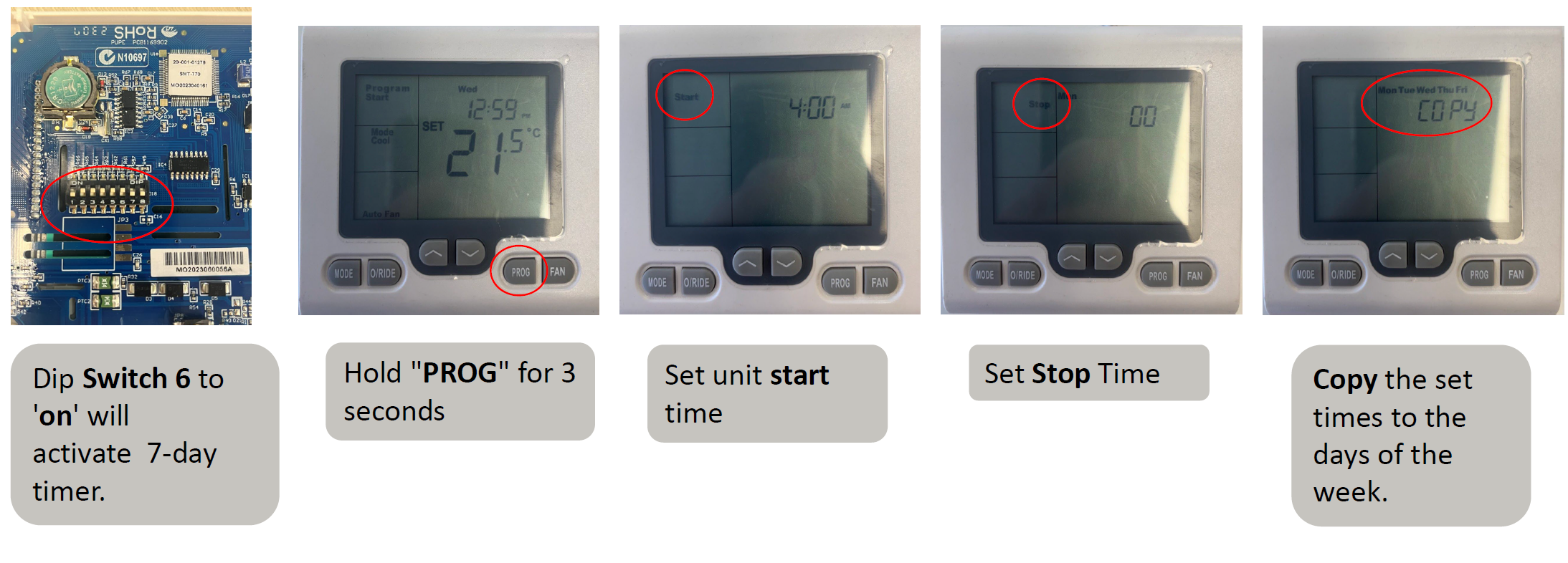
| 6 | ON | Programmable controller / 7-day timer enabled |
| 7 | OFF | Factory position |
| 8 | OFF | Factory position |
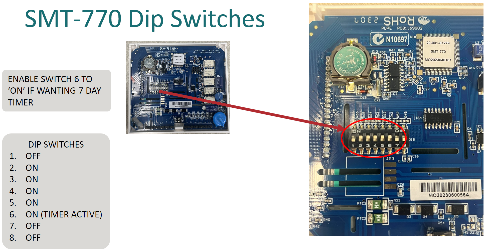
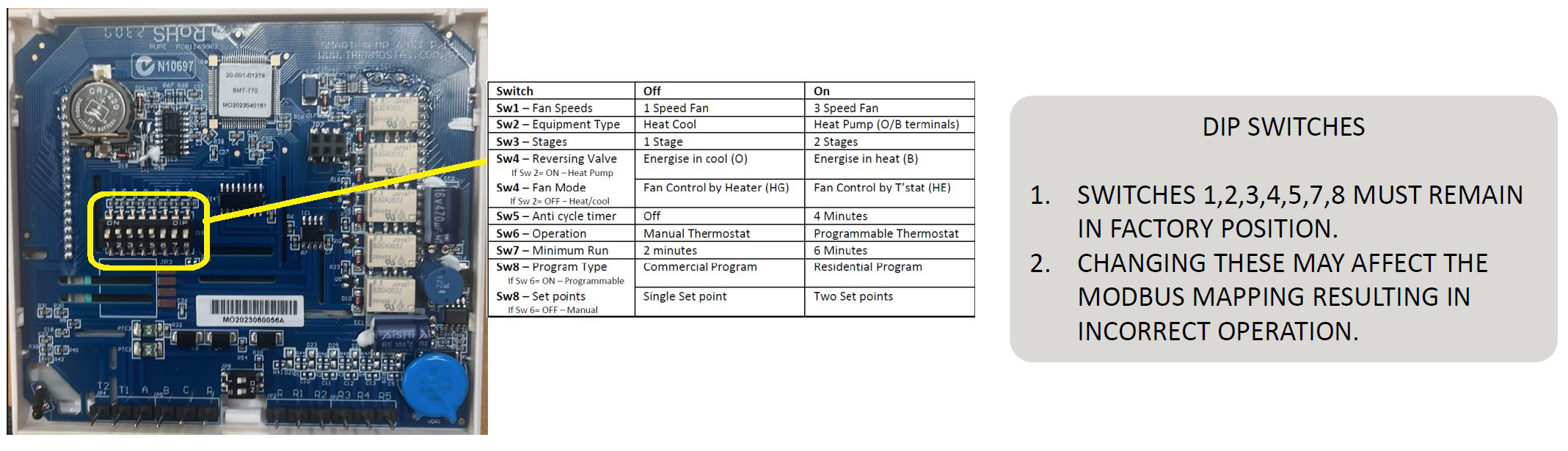
Switches 1, 2, 3, 4, 5, 7 and 8 must remain in the specified factory positions. Altering them can change the thermostat operating profile and may disrupt Modbus mapping.
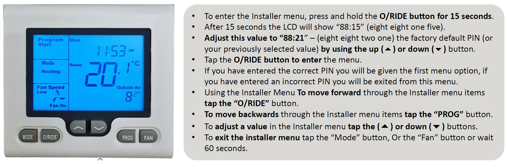
Entering the installer menu
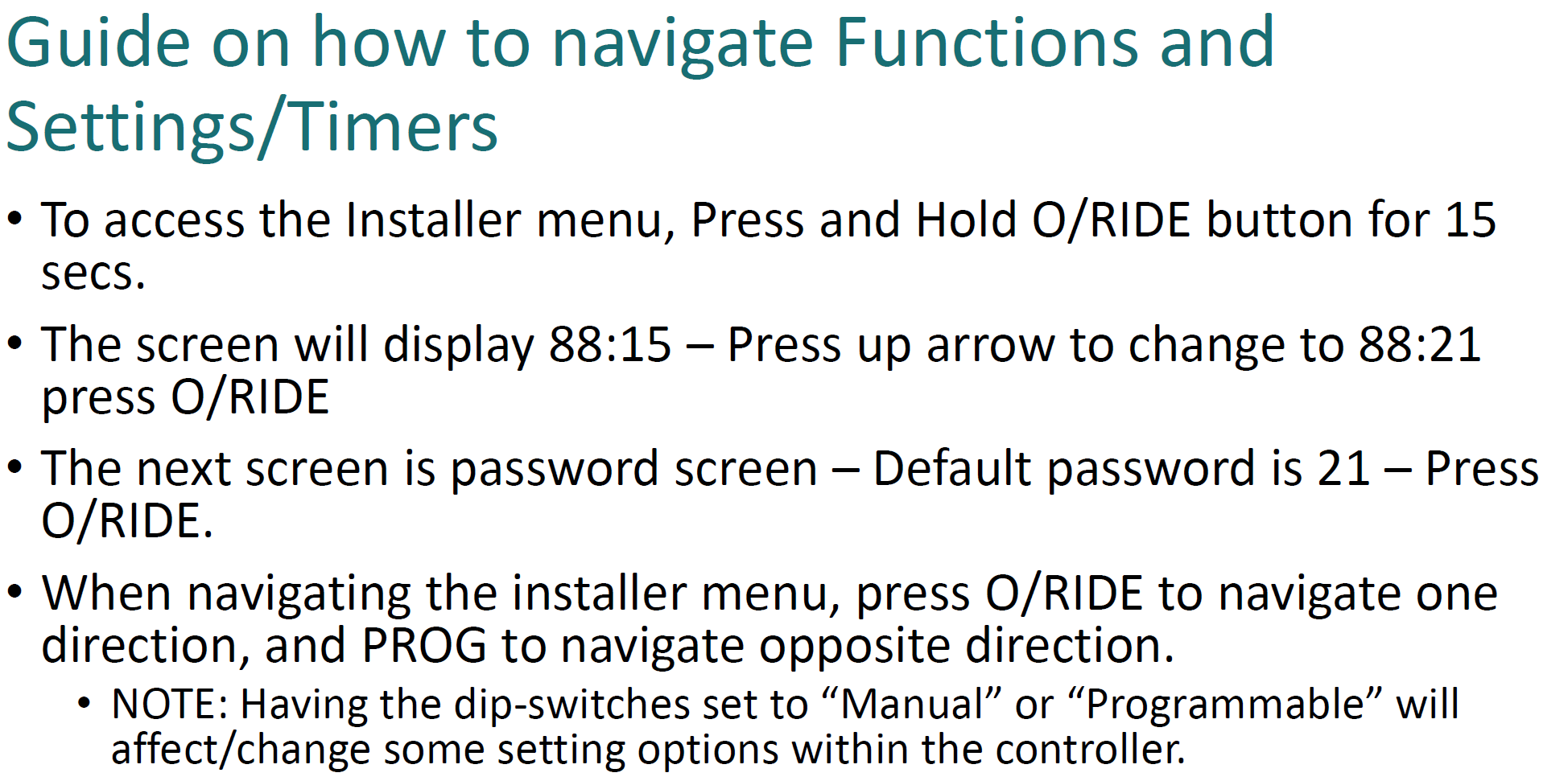
| 1 | Press and hold O/RIDE for 15 seconds. |
| 2 | The display shows 88:15. Use the arrow buttons to change it to 88:21. |
| 3 | Press O/RIDE to enter the installer menu. |
| 4 | Use O/RIDE to move forward and PROG to move backwards through menu items. |
| 5 | Use the up and down arrows to change values. |
| 6 | Press MODE or FAN, or wait 60 seconds, to exit. |
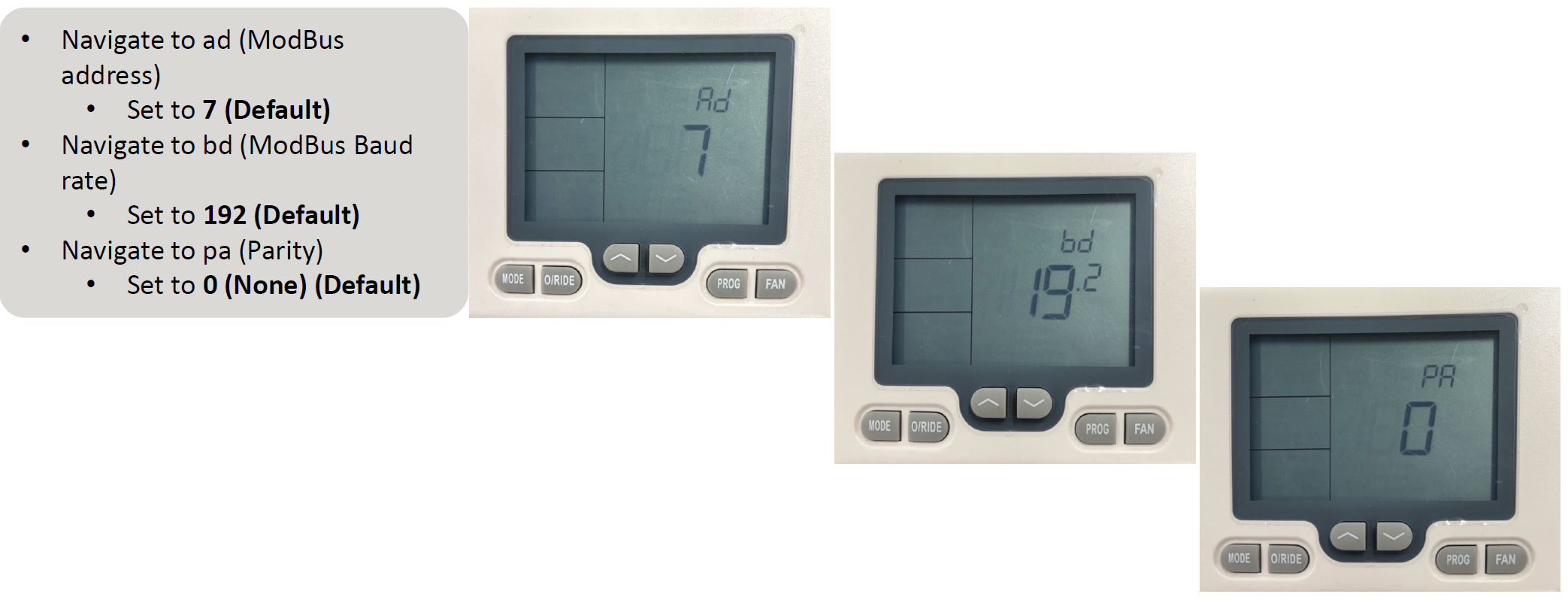
Required Modbus settings
| Menu | Setting | Value |
|---|---|---|
| Ad | Modbus address | 7 |
| bd | Modbus baud rate | 19.2 / 19200 |
| PA | Parity | 0 / None |
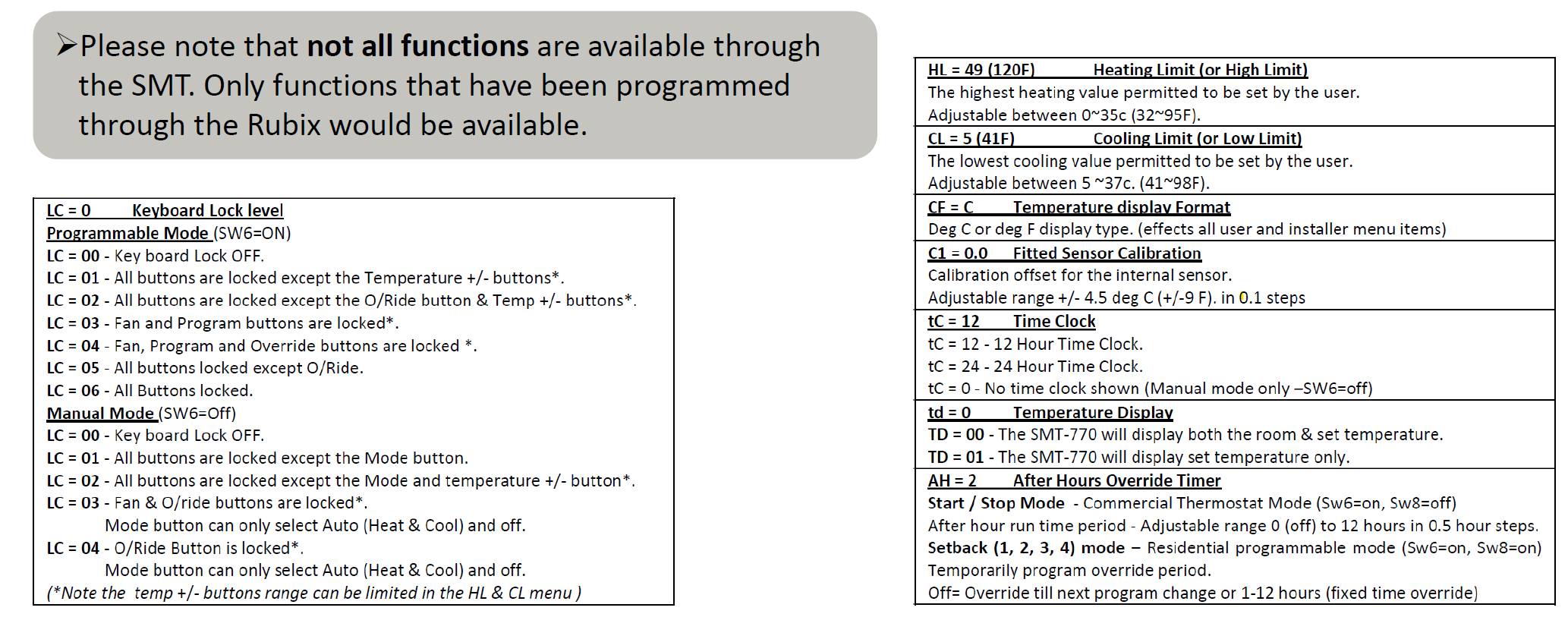
Common SMT-770 functions
| Function | Purpose |
|---|---|
| LC | Keyboard lock level |
| HL | Maximum heating setpoint |
| CL | Minimum cooling setpoint |
| CF | Celsius / Fahrenheit display |
| C1 | Internal sensor calibration |
| tC | 12-hour or 24-hour clock |
| td | Room and set-temperature display selection |
| AH | After-hours override duration |
5. SMT-770 seven-day timer
DIP switch 6 must be ON for the programmable seven-day timer.
| 1 | Hold PROG for approximately 3 seconds. |
| 2 | Set the required unit start time. |
| 3 | Set the required stop time. |
| 4 | Copy the programmed times to the required days of the week. |
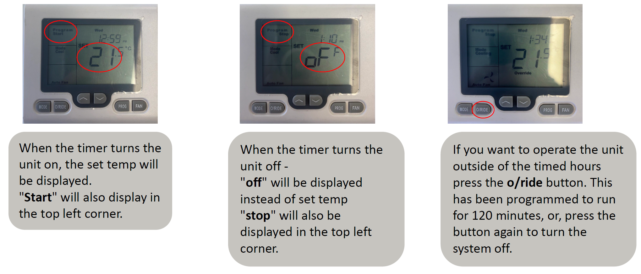
When the timer is active, START or STOP appears in the top-left of the display. The O/RIDE button can temporarily operate the system outside scheduled hours. The illustrated configuration uses a 120-minute override.
6. Communication troubleshooting
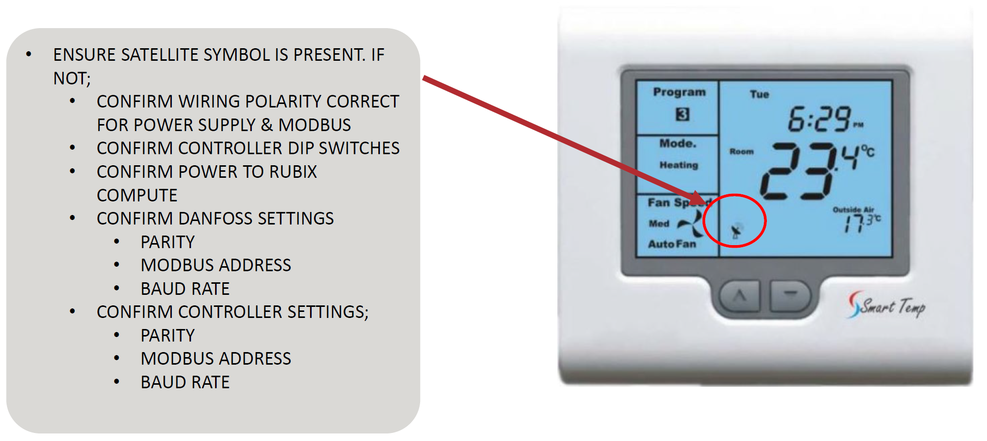
The satellite/communication symbol on the SMT-770 display indicates communication status. If it is missing or crossed out, complete the following checks.
| 1 | Confirm 24 V AC supply at SMT-770 Power 24 and 24C. |
| 2 | Confirm RS485 polarity from COMS A/B to D1+/D1-. |
| 3 | Confirm SMT-770 DIP switches match the required positions. |
| 4 | Confirm Rubix has 24 V DC power and both status LEDs are illuminated. |
| 5 | Confirm Danfoss parity, Modbus address and baud rate. |
| 6 | Confirm SMT-770 Ad = 7, bd = 19.2 and PA = 0. |
7. Important operating notes
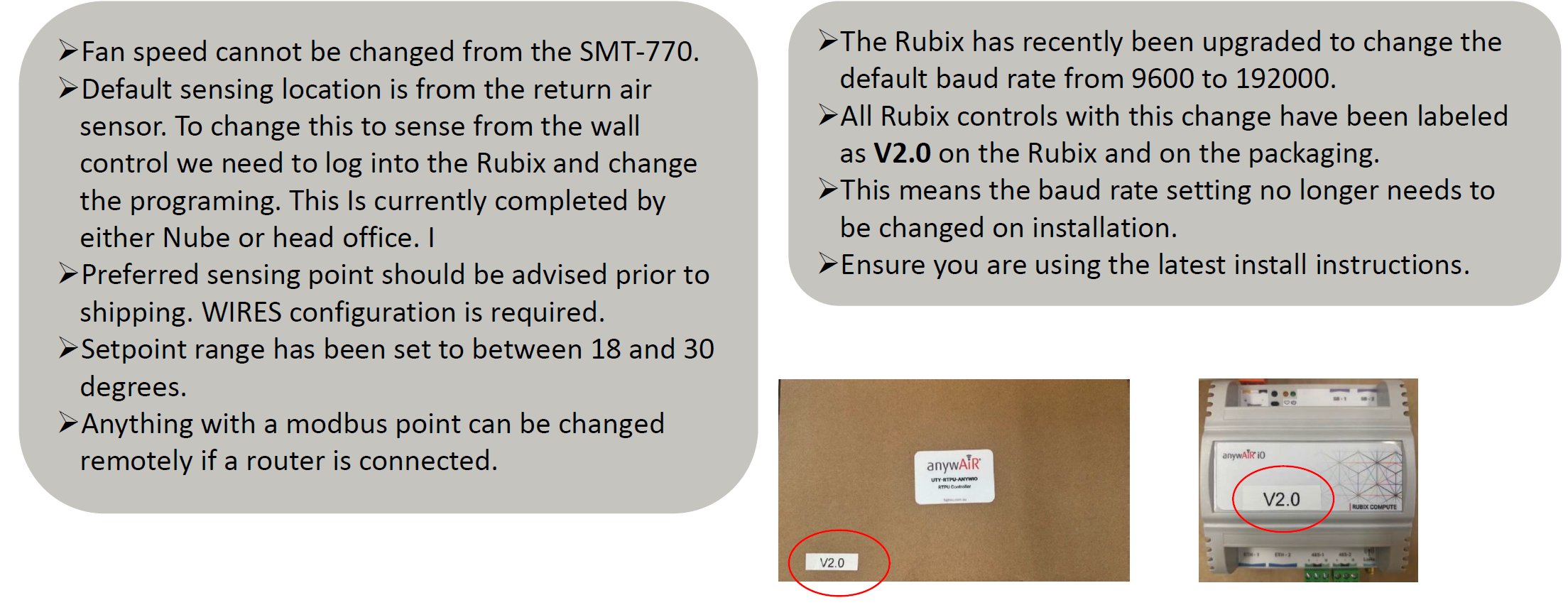
- Fan speed cannot be changed directly from the SMT-770.
- Default temperature sensing is from the RTPU return-air sensor.
- Changing sensing to the wall controller requires Rubix programming and should be specified before shipment.
- The configured setpoint range is generally 18°C to 30°C.
- Modbus points can be adjusted remotely when a router is connected and authorised access is available.
- Rubix V2.0 units are configured for 19200 baud and are labelled V2.0 on the enclosure and packaging.
- Always use the latest installation instructions and confirm the Rubix software version before changing baud settings.
8. Commissioning checklist
| Check | Done |
|---|---|
| 240 V AC isolated and verified before wiring | ☐ |
| 24 V DC polarity confirmed at Rubix | ☐ |
| 24 V AC measured at SMT-770 | ☐ |
| RS485 polarity confirmed at all devices | ☐ |
| Rubix connected through 485-1 only | ☐ |
| SMT-770 DIP switches verified | ☐ |
| Modbus address, baud and parity verified | ☐ |
| Satellite/communication icon present | ☐ |
| Start, stop, mode and setpoint commands tested | ☐ |
| Timer and override tested where enabled | ☐ |
This article is based on the supplied General Australia and New Zealand installation diagrams. Confirm the applicable RTPU wiring diagram, Danfoss configuration, Rubix software version and current installation instructions before completing or modifying the installation.