TABLE OF CONTENTS Safety Considerations 2 1.0 Introduction 4 2.0 Installation Guide 4 3.0 Chiller Structure 12 4.0 Refrigerant 14 5.0 Refrigeration Cycle 16 6.0 Motor and Power Electronics Cooling 17 7.0 Starter Device 17 8.0 Electronic Expansion Valve (EEV) 18 9.0 Control System 22 10.0 Preparation Before Startup 34 11.0 Initial Startup 36 12.0 Operation Guide 36 13.0 Maintenance 37 14.0 Troubleshooting Guide 38 15.0 Typical Piping Diagram 39 16.0 Typical Wiring Diagram 44 17.0 Appendixes 52 SAFETY CONSIDERATIONS This document is a guide of after sale service when water-cooled centrifugal chillers are operated under designed condition. Installers, servicers and installing contractors must acknowledge the potential hazards that could result in equipment damage, personal injury and death. Operator and service technician must be fully trained and officially authorized. Before any action of installation, operation and maintenance, operators are required to understand and observe the operation guide and safety precautions in this document based on the observance of National Standard and Code. | DANGER! | | In accordance with the latest edition of ANSI/ASHRAE 15 (American National Standards Institute/American Society of Heating, Refrigeration, and Air Conditioning Engineers), DO NOT VENT safety valves within a building. Outlet from valves must be vented outdoors. PROVIDE adequate ventilation, especially for enclosed and low overhead spaces. Inhalation of high concentrations of vapor is harmful and may cause heart irregularities, unconsciousness, or death. Misuse can be fatal. Vapor is heavier than air and reduces the amount of oxygen available for breathing. Product causes eye and skin irritation. Decomposition products are hazardous. DO NOT USE OXYGEN to purge lines or to pressurize a chiller for any purpose. DO NOT USE air for leak testing. Use only refrigerant or dry nitrogen. NEVER EXCEED specified test pressures, verify the allowable test pressure by checking the instruction literature and the design pressures on the chiller nameplate. DO NOT VALVE OFF any safety device. BE SURE that all pressure safety valves are properly, installed and functioning before operating any chiller. PLEASE be aware of ELECTRIC SHOCK! Must cut off the power when wiring. DO NOT work on high-voltage equipment unless you are qualified. ONLY qualified people can work on electrical components. Do not work on control box until ALL POWER IS OFF, which can be done through the main breaker. DO NOT WORK ON electrical components, including control panels, switches, starter cabinet and oil heater etc., until you ensure ALL POWER IS OFF & wait at least 10 minutes; because residual voltage can leak from capacitors or other electrical components. LOCK OPEN AND TAG electrical circuits during servicing. IF WORK IS INTERRUPTED, confirm that all circuits are de-energized before resuming work. During installation, commissioning, operation and maintenance, the engineers must be equipped with safety glasses, gloves, shoes and protective clothing. |
SAFETY CONSIDERATIONS | WARNING! | | All installation parts must be maintained by the personnel in charge, in order to avoid material deterioration and injuries to people. Any Fault or leak must be repaired immediately by authorized technician. Only qualified personnel familiar with the construction can work on the refrigeration components, and all welding job must be done by qualified welder. The refrigerant must be discharged and leaking point must be examined and repaired once any leak occurs. The weight of refrigerant should be charged after repair refers to the nameplate of the chiller. If stop valves are applied to the chiller, the refrigerant could be stored in the vessel rather than discharged during repair. The refrigerant is only being charged through liquid tube and at the meantime make sure there is water flow in the vessel. DO NOT attempt to vent Oxygen to any pipe on the chiller because Oxygen gas reacts violently with oil, grease, and other common substances. The chiller must work under its maximum designed pressure. If water system is installed and the environment temperature is under zero degree, the drain valve must be open to empty the tube water. Fire extinguisher must be easy to take once a fire occurs. DO NOT WELD OR FLAMECUT any refrigerant line or vessel until all refrigerant (liquid and Vapor) has been removed from chiller. Traces of Vapor should be displaced with dry air nitrogen and the work area should be well ventilated. Refrigerant in contact with an open flame produces toxic gases. AVOID SPILLING liquid refrigerant on skin or getting it into the eyes. USE SAFETY GOGGLES AND SAFETY GLOVES. Wash any spills from the skin with soap and water. If liquid refrigerant enters the eyes, IMMEDIATELY FLUSH EYES with water and consult a physician. DO NOT USE eyelets to lift any part of the machine or the complete machine. NEVER apply an open flame or live steam to refrigerant cylinder; otherwise it may result in dangerous overpressure. If necessary, use warm water under 43.3°C. DO NOT REUSE disposable (non-returnable) cylinders or attempt to refill them. It is DANGEROUS AND ILLEGAL. When cylinders are emptied, evacuate remaining gas pressure, loosen the collar and unscrew and discard the valve stem. DO NOT INCINERATE. During refrigerant operations, CHECK THE REFRIGERANT TYPE before adding refrigerant to the machine. The introduction of the wrong refrigerant can cause damage or malfunction to this machine. When applying refrigerant from other manufacturers, the refrigerant must meet the requirements of GENERAL AIRSTAGE material regulations. Make sure the relative pressure is 0 Pa before doing any work on any connection. PERIODICALLY INSPECT all valves, fittings, and piping for corrosion, rust, leaks, or damage. DO NOT LOOSEN a packing gland nut before checking that the nut has a positive thread engagement. |
| CAUTION! | | DO NOT WALK ON the refrigerant pipe in order to prevent it from damage. DO NOT climb over a chiller. Use platform, catwalk or staging and observe the safety operation rules. USE MECHANICAL EQUIPMENT (crane, hoist, etc.) to lift or move heavy components. Even if components are light, use mechanical equipment when there is a risk of slipping or losing your balance. BE AWARE that automatic restart schedule CAN ENGAGE TOWER FAN, OR PUMPS. Disconnect the power of the tower fans and pumps. USE only repair or replacement parts that meet the code requirements of the original equipment. DO NOT VENT OR DRAIN water boxes containing industrial brines, liquid, gases, or semisolids without the permission of your process control group. DO NOT LOOSEN water box cover bolts until the water box has been completely drained. DOUBLE-CHECK that coupling nut wrenches, dial indicators, or other items have been removed before rotating any shafts. PROVIDE A DRAIN connection in the vent line near each pressure relief device to prevent a build-up of condensate or rain water Do not short or jumper between terminations on circuit boards or modules, which may result in control or board failure. |
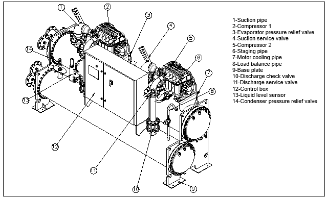
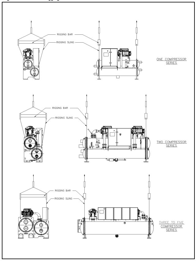
1.0 INTRODUCTION This manual is to provide all the necessary information for installation, operation and maintenance of the latest generation of the GENERAL AIRSTAGE Magnetic Bearing Variable Speed Centrifugal Chillers. DCLC-M has been manufactured under a careful quality control system. If the chiller is installed, operated and maintained with care and attention to the instructions contained herein, it will give many years of satisfactory service. Only experienced and qualified air conditioning equipment personnel can install, operate and maintain this equipment. The primary technical parameters can be found on the nameplate of the chiller. The usage of the unit should accordance with pressure vessel standards. 2.0 INSTALLATION GUIDE 2.1 BRIEF INTRODUCTION 2.1.1 Summary The DCLC-M chiller is factory assembled, wired, leak tested, insulated and delivered to the site. Installation consists primarily of establishing water and electrical services to the chiller. The uploading, rigging, foundation, site wiring, site piping, and insulation of external piping are the responsibility of the contractor and/or customer. Figure 2.1 General DCLC-M Unit Components (for reference only, actual unit must refer certified drawing) 1-Suction pipe 2-Compressor 1 3-Evaporator pressure relief valve 4-Suction service valve 5-Compressor 2 6-Staging pipe 7-Motor cooling pipe 8-Load balance pipe 9-Base plate 10-Discharge check valve 11-Discharge service valve 12-Control box 13-Liquid level sensor 14-Condenser pressure relief valve 2.1.2 Technical Information Know well following information before installation: Contract and Technical Agreement Unit Location Drawing Rigging Requirement Connection Drawing and Details Electrical drawing Installation information of starters Official drawings provided by GENERAL AIRSTAGE 2.0 INSTALLATION GUIDE 2.2 INSTALLATION 2.2.1 Check and accept the chiller ! CAUTION: Do not open any valves or loosen any connections. The standard DCLC-M chiller is shipped with refrigerant. 2.2.1.1 Inspect Transportation Qualify Check if there is any damage occurred during delivery before unloading. If damaged or moved, have it examined, confirmed and taken photos by transportation inspectors before unloading, and then analyze the reasons and responsible party. Inspect if the chiller and accessories are intact according to the package list. If there is anything missed, please immediately notify the nearest GENERAL AIRSTAGE representative. Leave all parts in original packages until the installation. 2.2.1.2 Confirm the chiller and accessories Check and confirm the chiller and accessories according to the contract, technical agreement and package list, if there is something missed, please immediately notify GENERAL AIRSTAGE. The models of the chiller and heat exchangers are noted in the nameplates. 2.2.1.3 Storage Protect the chiller and control box from being affected with damp during storage. Do not remove the cover plates before installation. Prevent dusts and impurities enter the system while installing. The chiller should be prevented from freezing after water circuits have been installed. For standard chiller,when the environment temperature is equal/below 0°C,open water drains in the waterbox and removes all water from cooler and condenser. Leave drains open during installation. 2.2.2 Rigging Three, four & five compressors models are shipped with base, if applicable, remove the base when chiller reached site. To lift a chiller, read this rigging instruction and refer to the DCLC-M Rigging Guide (Figure 2.2.2). The rigging bar and rigging sling do not come with the chiller. !Warning: Lift the chiller only from points indicated in Figure 2.2.2,Lifting from other than these points may result in serious damage to the unit and personal injury. Each rigging sling must be able to withstand the entire weight of the chiller. Rigging equipment must be able to withstand the entire weight of the chiller. Do not move/lift the chiller using forklift. !Note: Use rigging bar to maintain safety distance and prevent chiller components from scraped/damaged by the rigging sling. Adjust rigging sling length to leveling the chiller horizontally flat from all sides, do not move the chiller if it is sloping/tend to flip over. Damage will happen when impact, be sure that the units will be transported smoothly and safely. When transporting the module with rolling bars, do protect the units from overturning. 2.0 INSTALLATION GUIDE
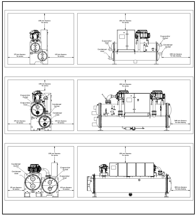
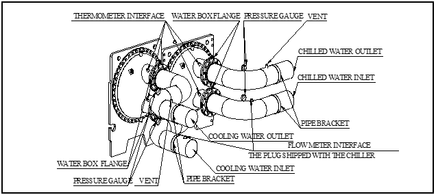
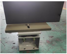
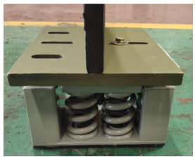
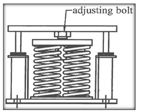
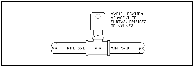
Figure 2.2.2 DCLC-M Rigging Guide 2.0 INSTALLATION GUIDE 2.2.3 The condition of the installation field 1. The chiller room must away from fire source and tinder; 2. The chiller room with indoor temperature below 43.3⁰C, good ventilation, with no corrosive surroundings; 3. The foundation is strong enough to support the running weight; 4. Achieve draining completely around the unit and the chiller room; 5. The chiller room should have enough space for operating and maintenance (refer to Figure 2.2.3) Figure 2.2.3 DCLC-M Unit Maintenance Space 2.0 INSTALLATION GUIDE 2.2.4 Pipe Connection 2.2.4.1 Water System Pipe Connection An example of water system arrangement and installation can refer to Figure 2.2.4. Offset pipe flanges for maintenance and pipe cleaning; Provide openings on pipes for pressure gages and thermometers; Install flow meter (if applicable) on both inlet and outlet of chilled water; Install air vents at high points of the pipes; Install perpetual filter at the water inlet; Install brackets under pipes where needed; The water system pipe should meet entering from the lower one and leaving from the upper one; To prevent insulation from damaging by welding sparks, please cover a wet canvas while welding; Remove all sensors before installation, re-assemble them after installation/welding. Figure 2.2.4 Example of Piping Installation (for reference only) !Caution: The water pipeline should be connected to the pump and chiller with flexible connector, and should be supported by a separate stand and not by the pump and chiller. To avoid scaling in both condenser and evaporator, water pipeline should be cleaned before starting chiller. When using acid cleaner, chiller should be bypassed. Maximum design water pressure of standard model chiller is 1.0MPa, higher water pressure vessel is available as an option. Whatever cooling load changes to, chilled water flow should be constant. If water flow deviates from the design value +10% / -50%, chiller can operate normally. While variable water flow would cause leaving water temperature uncontrollably, controlling rate of entering chilled water temperature change less than 1.1°C per minute is necessary. If using two way valve to control water flow into cooling coil, chilled water should keep constant by some measures, for example, using automatic regulating valve .If the chilled water system is designed for both cooling and heating ,Manual or automatic stop valve is needed for evaporator to isolate hot water,at the same time, inlet evaporator water temperature should less than 32°C. Cooling water flow should be constant also and deviating from the design value +10% / -15% is available. Rate of entering chilled water temperature change should be less than 0.6°C per minute,water flow and temperature fluctuate would cause leaving chilled water temperature uncontrollably .Rate of entering condenser water temperature change should not too fast when using cooling tower. When entering condenser water temperature is less than 15°C,it’s hard to establish pressure difference,which would cause cooling problem and damage to the motor and bearing. (Please contact GENERAL AIRSTAGE after-sales staff to get technical support of specific solution.) 2.0 INSTALLATION GUIDE 2.2.4.2 Spring Isolator Spring Isolator are optional items, if required, can purchase from GENERAL AIRSTAGE. Front View, Photo A Side View, Photo B Picture C Note: Photos & Picture shown are example, for reference only, may differ from actual. Statement: 1. Secure each Spring Isolator with a bolt, only one bolt is required (see Photo A). 2. Position the Spring Isolator across the Vessel Tube Sheet (see Photo B). 3. Chiller must horizontally flat & stable, Adjust the adjusting bolt to leveling the Chiller if required. 2.0 INSTALLATION GUIDE 2.2.4.3 Water Flow Switch A flow switch must be installed at evaporator outlet to proof the chilled liquid flow through the evaporator. This is to prevent damage to the evaporator resulted by unit operation with insufficient fluid flow. Evaporator flow switch can be supplied as an optional item. The flow switch is factory shipped loose, field installed item. The flow switch must be located in a horizontal section on the pipe where there are at least five (5) pipe diameters on both sides of the flow switch before any other connections, as indicated in Figure below. The flow switch paddle must be adjusted to the size of pipe in which the paddle is installed, and the switch set to trip at approximately minimum operating flow rate. Refer to the unit wiring diagram for the electrical connections to interlock the Chilled Water Flow Switch (CWFS) with the control panel. Figure 2.2.4.3: Flow Switch The same flow switch can be also supplied as an optional item for condenser water flow detection. This may help to prevent high condenser pressure alarm which caused by condenser water flow loss. 2.2.5 Install Vent Piping To Safety Valves Refrigerant discharged into confined spaces can displace oxygen and cause asphyxiation. It is advised that the safety valve should discharge outdoors refer to ANSI/ ASHRAE 15 and location safety laws and regulations. The cross-sectional area of the relief pipe must at least equal the sum of the areas required for the individual relief pipes. (standard single valve flow area is 254mm2) Install pipe bracket where needed, ensure no load on the safety valve discharge pipe line. A length of the flexible tubing or piping near the device is essential on spring-isolated chillers. Cover the outdoor vent with a rain cap and place a filter at the low point of the pipe. The opening pressure of the safety valve is 200PSI. 2.2.6 Electric Connection Wire connection must refer to the connection drawing and all electric application standards. The connecting drawing is for your reference only, actual installation refer to installation drawing on site. Do not start the compressor when the unit is vacuum (even just check the diversion), also not add any detection voltage. Or the motor isolation may be damaged seriously. 2.2.6.1 Connect Control Input Standby interlocking closing down, closing down in distant place, starting up in distant place and water-break contact of the chilled water are connected on site. 2.2.6.2 Connect Control Output Connect output device, chilled pump, cooling pump, cooling tower, standby device and the devices needed in the connection drawing on site. 2.0 INSTALLATION GUIDE 2.2.6.3 Connect Control Box Before connect wires, please ensure to meet the following requirements. Ambient temperature range: -5~+45°C. Relative humidity: <90%, without condensation. The height above sea level where the unit is installed is not exceed 2000m. Pollution grade: 3, conductive contamination or dry nonconductive contamination become conductive due to condensation. There is no serious quake on the site, the incline angle with vertical does not exceed 5°. Power supply range: compared to rated voltage, the error is ±10%. The starter cabinet is 3 phase 4 wires. According to the wiring diagram on the power supply to main circuit breaker into the line of copper platoon, the wire can only use copper wires, used motor should be reliable grounding. 2.2.7 Install Insulation On Site Install insulation on site after unit installation. If have no special requirements, the unit has already insulated in factory. Insulation of external piping is by others. 2.2.8 Others The losses due to water quality is undertook by the user. The user should check the water quality before installation and during operating. Poor water quality can cause the high-efficiency tube fouling and reduce the efficiency of heat exchange, it may corrode and cause the leakage of tubes, affect the unit normal operation. 2.3 INSTALLATION CHECK BEFORE STARTUP GENERAL AIRSTAGE will supply service of installation check, initial startup and operation. After the chiller is installed, piped and wired according to this manual, inform GENERAL AIRSTAGE local office to arrange initial startup service by contract. Three copies of “Installation Checklist” are required for this service. 3.0 CHILLER STRUCTURE 3.1 CHILLER NAMEPLATE DCLC-M unit nameplate located on the control box, contains centrifugal chiller model, power supply and others information. 3.2 SYSTEM COMPONENTS The system components contain compressor, motor, guide vane actuator, evaporator, condenser, Micro-computer control panel. 3.2.1 Compressor DCLC-M Chillers visualized oil-free high technology that use magnetic field, so that the rotor is suspended, no mechanical contact when rotating. The Magnetic Bearing Oil Free compressors are with built-in magnetic suspension bearing, when the unit is powered on, the impeller shaft will be suspended, magnetic levitation bearing internal sensors and the corresponding control technology ensures that the rotor suspended in the center of the bearing, and no mechanical contact to the bearing. The lubrication are no longer needed in the compressor, all the annoyance because of lubricating oil is gone. The Magnetic Bearing Oil Free compressors adopt digital frequency conversion technology, high-speed direct technology, two stage compression technology and liquid level control technology. It is the world's advanced technologies with high efficiency and energy saving, simple maintenance and compact structure, low noise and wide scope of operation, etc. 3.2.2 Guide Vane Actuator Cooling capacity control of the chiller is achieved by adjusting the degree of opening of the inlet guide vane to adjusting the volume flow rate. The compressor speed as well as guide vane to carry out double regulation of cooling capacity, at the same time, it will avoid compressor surge at low load. Figure 3.2 Nomenclature Of DCLC-M DCLC 300 M D D H465 E F GENERAL AIRSTAGE Centrifugal Liquid ChillerBlank : R134a F : R513A ModelE : With Economizer Blank : Without Economizer Magnetic Bearing Oil Free Compressor Vessels Model Compressor ModelCompressor Quantity / Combination 3.0 CHILLER STRUCTURE 3.2.3 Evaporator The cooler is horizontal shell-tube type with inside high-efficiency tube. There have intermediate support sheets along the tube. Install an eliminator on the top of the cooler to prevent liquid refrigerant from entering the compressor. 3.2.4 Condenser The condenser is also horizontal shell-tube type with inside high-efficiency tube, its main construction is the same with cooler. Install a buffer along the axial direction to prevent the high speed superheat vapor from the compressor rush the condenser tube directly. In the piping under the condenser which connected with cooler there install EEV/Orifice which throttles the high pressure and temperature liquid under the condenser to low pressure and temperature liquid, and then enter to the cooler. Approach temperature (the difference between saturated refrigerant temperature and leaving water temperature) could be an indication of tube fouling. In general, the condenser approach temperature is about 2°F. An increase of two degrees or more in approach temperature may indicates excessive tube fouling could be present. 3.2.5 Micro-Computer Control Panel DCLC-M adopt the state of control system to ensure the chiller operate safely and reliably. Large display screen, surface is practical and pretty. Directly control and set the parameters of the chiller operation on the screen, convenient operation and intuitionist. The screen displays graphic, parameters of the chiller operation and achieve constant monitoring. The start-stop and automatic control procedures can be adjusted, user can achieve the unit safe and reliable start, stop and adjust operation automatically through simply click on a button. Switch automatic and manual control mode easily. Multiple kinds of items protection and malfunction used to make the chiller operation secure, and the last 99 items of the failure parameter can be recorded. The control system can carry out an initial diagnosis, indicating the possible cause of the malfunction automatically. RS 485 interface for Standard Modbus & Bacnet IP protocol available and Bacnet MSTP, LONWORKS, N2 protocol (optional) DCLC-M series Magnetic centrifugal chiller power electric control part is mainly composed of main isolator, ac line reactor, EMI/EMC filter (optional), and the fast acting fuse. Control the compressor start-stop, load, important parameter acquisition unit, I/O board through the machine to collect important parameters inside the compressor. 4.0 REFRIGERANT DCLC-M use environmental friendly non ozone depletion refrigerant R134a or R513A. The pressure-temperature relation under saturated condition can refer to below R134a table & R513A table. R134a | R-134a PRESSURE / TEMPERATURE PROPERTIES (PSIG-F) | | | | | | | | | | | Pressure | Temp. | Pressure | Temp. | Pressure | Temp. | Pressure | Temp. | Pressure | Temp. | | 0 | -14.7 | 53 | 56.9 | 106 | 90.9 | 159 | 115.0 | 212 | 134.1 | | 1 | -12.0 | 54 | 57.7 | 107 | 91.5 | 160 | 115.4 | 213 | 134.4 | | 2 | -9.5 | 55 | 58.5 | 108 | 92.0 | 161 | 115.8 | 214 | 134.7 | | 3 | -7.1 | 56 | 59.3 | 109 | 92.5 | 162 | 116.2 | 215 | 135.1 | | 4 | -4.8 | 57 | 60.1 | 110 | 93.0 | 163 | 116.6 | 216 | 135.4 | | 5 | -2.6 | 58 | 60.9 | 111 | 93.5 | 164 | 117.0 | 217 | 135.7 | | 6 | -0.5 | 59 | 61.6 | 112 | 94.0 | 165 | 117.4 | 218 | 136.0 | | 7 | 1.5 | 60 | 62.4 | 113 | 94.5 | 166 | 117.7 | 219 | 136.4 | | 8 | 3.5 | 61 | 63.1 | 114 | 95.0 | 167 | 118.1 | 220 | 136.7 | | 9 | 5.3 | 62 | 63.9 | 115 | 95.5 | 168 | 118.5 | 221 | 137.0 | | 10 | 7.2 | 63 | 64.6 | 116 | 96.0 | 169 | 118.9 | 222 | 137.3 | | 11 | 8.9 | 64 | 65.3 | 117 | 96.5 | 170 | 119.3 | 223 | 137.6 | | 12 | 10.6 | 65 | 66.0 | 118 | 97.0 | 171 | 119.7 | 224 | 138.0 | | 13 | 12.3 | 66 | 66.8 | 119 | 97.5 | 172 | 120.0 | 225 | 138.3 | | 14 | 13.9 | 67 | 67.5 | 120 | 98.0 | 173 | 120.4 | 226 | 138.6 | | 15 | 15.5 | 68 | 68.2 | 121 | 98.4 | 174 | 120.8 | 227 | 138.9 | | 16 | 17.0 | 69 | 68.9 | 122 | 98.9 | 175 | 121.2 | 228 | 139.2 | | 17 | 18.5 | 70 | 69.5 | 123 | 99.4 | 176 | 121.5 | 229 | 139.5 | | 18 | 20.0 | 71 | 70.2 | 124 | 99.9 | 177 | 121.9 | 230 | 139.8 | | 19 | 21.4 | 72 | 70.9 | 125 | 100.3 | 178 | 122.3 | 231 | 140.1 | | 20 | 22.8 | 73 | 71.6 | 126 | 100.8 | 179 | 122.6 | 232 | 140.4 | | 21 | 24.1 | 74 | 72.2 | 127 | 101.3 | 180 | 123.0 | 233 | 140.8 | | 22 | 25.4 | 75 | 72.9 | 128 | 101.7 | 181 | 123.4 | 234 | 141.1 | | 23 | 26.7 | 76 | 73.5 | 129 | 102.2 | 182 | 123.7 | 235 | 141.4 | | 24 | 28.0 | 77 | 74.2 | 130 | 102.7 | 183 | 124.1 | 236 | 141.7 | | 25 | 29.2 | 78 | 74.8 | 131 | 103.1 | 184 | 124.5 | 237 | 142.0 | | 26 | 30.5 | 79 | 75.5 | 132 | 103.6 | 185 | 124.8 | 238 | 142.3 | | 27 | 31.7 | 80 | 76.1 | 133 | 104.0 | 186 | 125.2 | 239 | 142.6 | | 28 | 32.8 | 81 | 76.7 | 134 | 104.5 | 187 | 125.5 | 240 | 142.9 | | 29 | 34.0 | 82 | 77.3 | 135 | 104.9 | 188 | 125.9 | 241 | 143.2 | | 30 | 35.1 | 83 | 78.0 | 136 | 105.3 | 189 | 126.3 | 242 | 143.5 | | 31 | 36.2 | 84 | 78.6 | 137 | 105.8 | 190 | 126.6 | 243 | 143.8 | | 32 | 37.3 | 85 | 79.2 | 138 | 106.2 | 191 | 127.0 | 244 | 144.1 | | 33 | 38.4 | 86 | 79.8 | 139 | 106.7 | 192 | 127.3 | 245 | 144.4 | | 34 | 39.5 | 87 | 80.4 | 140 | 107.1 | 193 | 127.7 | 246 | 144.7 | | 35 | 40.5 | 88 | 81.0 | 141 | 107.5 | 194 | 128.0 | 247 | 145.0 | | 36 | 41.5 | 89 | 81.5 | 142 | 108.0 | 195 | 128.4 | 248 | 145.3 | | 37 | 42.5 | 90 | 82.1 | 143 | 108.4 | 196 | 128.7 | 249 | 145.6 | | 38 | 43.5 | 91 | 82.7 | 144 | 108.8 | 197 | 129.1 | 250 | 145.9 | | 39 | 44.5 | 92 | 83.3 | 145 | 109.2 | 198 | 129.4 | 251 | 146.2 | | 40 | 45.5 | 93 | 83.9 | 146 | 109.7 | 199 | 129.7 | 252 | 146.4 | | 41 | 46.4 | 94 | 84.4 | 147 | 110.1 | 200 | 130.1 | 253 | 146.7 | | 42 | 47.4 | 95 | 85.0 | 148 | 110.5 | 201 | 130.4 | 254 | 147.0 | | 43 | 48.3 | 96 | 85.6 | 149 | 110.9 | 202 | 130.8 | 255 | 147.3 | | 44 | 49.2 | 97 | 86.1 | 150 | 111.3 | 203 | 131.1 | 256 | 147.6 | | 45 | 50.1 | 98 | 86.7 | 151 | 111.8 | 204 | 131.4 | 257 | 147.9 | | 46 | 51.0 | 99 | 87.2 | 152 | 112.2 | 205 | 131.8 | 258 | 148.2 | | 47 | 51.9 | 100 | 87.8 | 153 | 112.6 | 206 | 132.1 | 259 | 148.5 | | 48 | 52.7 | 101 | 88.3 | 154 | 113.0 | 207 | 132.4 | 260 | 148.7 | | 49 | 53.6 | 102 | 88.8 | 155 | 113.4 | 208 | 132.8 | 261 | 149.0 | | 50 | 54.4 | 103 | 89.4 | 156 | 113.8 | 209 | 133.1 | 262 | 149.3 | | 51 | 55.3 | 104 | 89.9 | 157 | 114.2 | 210 | 133.4 | 263 | 149.6 | | 52 | 56.1 | 105 | 90.4 | 158 | 114.6 | 211 | 133.8 | 264 | 149.9 |
4.0 REFRIGERANT R513A | R-513A PRESSURE / TEMPERATURE PROPERTIES (PSIG-F) | | | | | | | | | | | Pressure | Temp. | Pressure | Temp. | Pressure | Temp. | Pressure | Temp. | Pressure | Temp. | | 0 | -21.0 | 53 | 51.7 | 106 | 86.9 | 159 | 111.8 | 212 | 131.5 | | 1 | -18.4 | 54 | 52.5 | 107 | 87.4 | 160 | 112.2 | 213 | 131.9 | | 2 | -15.9 | 55 | 53.3 | 108 | 88.0 | 161 | 112.6 | 214 | 132.2 | | 3 | -13.5 | 56 | 54.1 | 109 | 88.5 | 162 | 113.0 | 215 | 132.5 | | 4 | -11.2 | 57 | 54.9 | 110 | 89.0 | 163 | 113.4 | 216 | 132.9 | | 5 | -8.9 | 58 | 55.7 | 111 | 89.5 | 164 | 113.8 | 217 | 133.2 | | 6 | -6.8 | 59 | 56.5 | 112 | 90.0 | 165 | 114.2 | 218 | 133.5 | | 7 | -4.8 | 60 | 57.3 | 113 | 90.6 | 166 | 114.6 | 219 | 133.9 | | 8 | -2.8 | 61 | 58.1 | 114 | 91.1 | 167 | 115.0 | 220 | 134.2 | | 9 | -0.9 | 62 | 58.8 | 115 | 91.6 | 168 | 115.4 | 221 | 134.5 | | 10 | 0.9 | 63 | 59.6 | 116 | 92.1 | 169 | 115.8 | 222 | 134.9 | | 11 | 2.7 | 64 | 60.4 | 117 | 92.6 | 170 | 116.2 | 223 | 135.2 | | 12 | 4.4 | 65 | 61.1 | 118 | 93.1 | 171 | 116.6 | 224 | 135.5 | | 13 | 6.1 | 66 | 61.8 | 119 | 93.7 | 172 | 117.0 | 225 | 135.8 | | 14 | 7.7 | 67 | 62.6 | 120 | 94.2 | 173 | 117.4 | 226 | 136.2 | | 15 | 9.3 | 68 | 63.3 | 121 | 94.7 | 174 | 117.8 | 227 | 136.5 | | 16 | 10.9 | 69 | 64.0 | 122 | 95.1 | 175 | 118.2 | 228 | 136.8 | | 17 | 12.4 | 70 | 64.7 | 123 | 95.6 | 176 | 118.6 | 229 | 137.1 | | 18 | 13.8 | 71 | 65.4 | 124 | 96.1 | 177 | 119.0 | 230 | 137.4 | | 19 | 15.3 | 72 | 66.1 | 125 | 96.6 | 178 | 119.3 | 231 | 137.8 | | 20 | 16.7 | 73 | 66.8 | 126 | 97.1 | 179 | 119.7 | 232 | 138.1 | | 21 | 18.1 | 74 | 67.5 | 127 | 97.6 | 180 | 120.1 | 233 | 138.4 | | 22 | 19.4 | 75 | 68.2 | 128 | 98.1 | 181 | 120.5 | 234 | 138.7 | | 23 | 20.7 | 76 | 68.8 | 129 | 98.5 | 182 | 120.9 | 235 | 139.0 | | 24 | 22.0 | 77 | 69.5 | 130 | 99.0 | 183 | 121.2 | 236 | 139.3 | | 25 | 23.3 | 78 | 70.2 | 131 | 99.5 | 184 | 121.6 | 237 | 139.7 | | 26 | 24.5 | 79 | 70.8 | 132 | 99.9 | 185 | 122.0 | 238 | 140.0 | | 27 | 25.7 | 80 | 71.5 | 133 | 100.4 | 186 | 122.3 | 239 | 140.3 | | 28 | 26.9 | 81 | 72.1 | 134 | 100.9 | 187 | 122.7 | 240 | 140.6 | | 29 | 28.1 | 82 | 72.8 | 135 | 101.3 | 188 | 123.1 | 241 | 140.9 | | 30 | 29.2 | 83 | 73.4 | 136 | 101.8 | 189 | 123.5 | 242 | 141.2 | | 31 | 30.4 | 84 | 74.0 | 137 | 102.3 | 190 | 123.8 | 243 | 141.5 | | 32 | 31.5 | 85 | 74.7 | 138 | 102.7 | 191 | 124.2 | 244 | 141.8 | | 33 | 32.6 | 86 | 75.3 | 139 | 103.2 | 192 | 124.5 | 245 | 142.1 | | 34 | 33.7 | 87 | 75.9 | 140 | 103.6 | 193 | 124.9 | 246 | 142.4 | | 35 | 34.7 | 88 | 76.5 | 141 | 104.1 | 194 | 125.3 | 247 | 142.7 | | 36 | 35.8 | 89 | 77.1 | 142 | 104.5 | 195 | 125.6 | 248 | 143.0 | | 37 | 36.8 | 90 | 77.7 | 143 | 105.0 | 196 | 126.0 | 249 | 143.3 | | 38 | 37.8 | 91 | 78.3 | 144 | 105.4 | 197 | 126.3 | 250 | 143.6 | | 39 | 38.8 | 92 | 78.9 | 145 | 105.8 | 198 | 126.7 | 251 | 143.9 | | 40 | 39.8 | 93 | 79.5 | 146 | 106.3 | 199 | 127.0 | 252 | 144.2 | | 41 | 40.8 | 94 | 80.1 | 147 | 106.7 | 200 | 127.4 | 253 | 144.5 | | 42 | 41.7 | 95 | 80.7 | 148 | 107.2 | 201 | 127.8 | 254 | 144.8 | | 43 | 42.7 | 96 | 81.3 | 149 | 107.6 | 202 | 128.1 | 255 | 145.1 | | 44 | 43.6 | 97 | 81.9 | 150 | 108.0 | 203 | 128.5 | 256 | 145.4 | | 45 | 44.5 | 98 | 82.4 | 151 | 108.4 | 204 | 128.8 | 257 | 145.7 | | 46 | 45.4 | 99 | 83.0 | 152 | 108.9 | 205 | 129.1 | 258 | 146.0 | | 47 | 46.3 | 100 | 83.6 | 153 | 109.3 | 206 | 129.5 | 259 | 146.3 | | 48 | 47.2 | 101 | 84.1 | 154 | 109.7 | 207 | 129.8 | 260 | 146.6 | | 49 | 48.1 | 102 | 84.7 | 155 | 110.1 | 208 | 130.2 | 261 | 146.9 | | 50 | 49.0 | 103 | 85.2 | 156 | 110.6 | 209 | 130.5 | 262 | 147.2 | | 51 | 49.8 | 104 | 85.8 | 157 | 111.0 | 210 | 130.9 | 263 | 147.5 | | 52 | 50.7 | 105 | 86.3 | 158 | 111.4 | 211 | 131.2 | 264 | 147.8 |
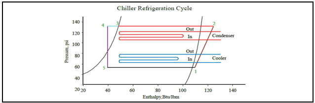
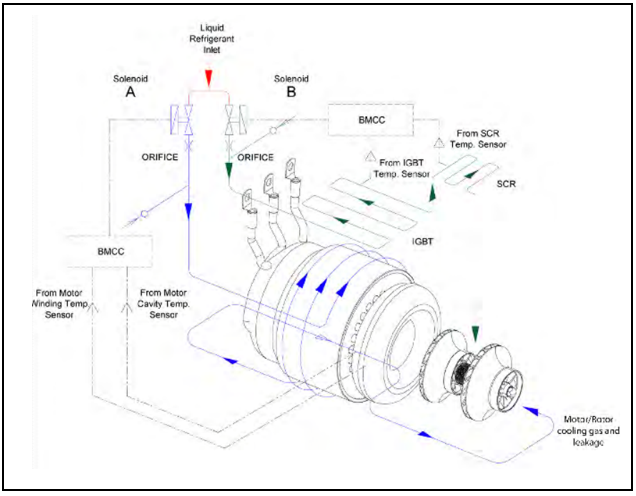
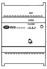
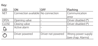
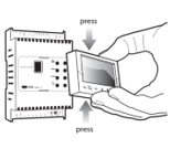
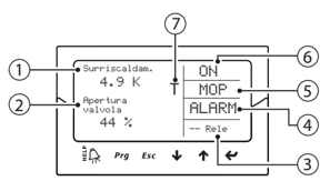
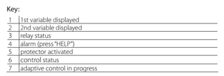
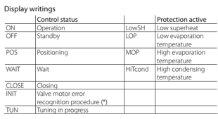
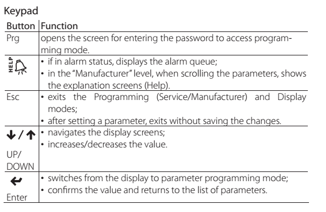
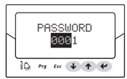
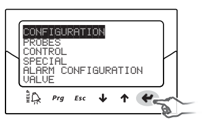
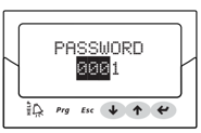
5.0 REFRIGERATING CYCLE Centrifugal chiller is a way of vapor-compress refrigerating, whose refrigerating principle is to increase the pressure and temperature of refrigerant vapor through imposing energy to it by the compressor, then process it with condensing, throttling procedures to turn it into refrigerant liquid of low pressure and temperature; with its evaporation into vapor in the cooler, it absorbs heat from the surrounding environment (refrigerant medium, such as chilled water) to bring down the temperature of refrigerant medium, thus achieving the goal of artificial refrigeration. It follows that the cycle of vapor-compress refrigeration includes 4 indispensable processes: compressing, condensing, throttling and evaporating. The following is the principle in details: 5.1 COMPRESSING After the refrigerant vapor in the cooler has been absorbed into the centrifugal compressor, the motor will impose energy to the vapor through compressor impeller, increasing its pressure and forcing it into the condenser; meanwhile, the temperature of refrigerant vapor increasing accordingly at the end of compressing process. 5.2 CONDENSING The refrigerant vapor of high pressure and temperature from the compressor will exchange heat with cooling water via tubes, under the saturation pressure (the corresponding condensing pressure to the condensing temperature) it condenses to liquid. By now, the temperature of the cooling water will increase as it absorbs heat from the refrigerant vapor. The cooling water temperature is directly relating to the condensing temperature. 5.3 SUB-COOLING the refrigerant condense to liquid in the condenser and the exchange heat with cooling water through the sub-cooler, the temperature is lower, so reduce the content of the flash vapor after throttling and improve the cooling capacity of mass unit. 5.4 THROTTLING The refrigerant liquid of high temperature and pressure from the bottom of the condenser will have decompression and expansion while passing the throttle orifice. As the pressure and temperature both decrease, it will enter the cooler as liquid of low pressure and temperature. 5.5 EVAPORATING The refrigerant liquid of low pressure and temperature will absorb heat from refrigerant medium (such as chilled water) in the cooler and evaporate into vapor. It brings down the temperature of the refrigerant medium to realize the goal of artificial refrigerating. The refrigerant vapor in the cooler will be absorbed and compressed by the compressor once again, repeating the 4 processes mentioned above. Continuous refrigerating is then realized in such a circulating process. The cooling capacity is directly proportional to refrigerant gas flow through the compressor. An adjustable guide vane is installed at the inlet of centrifugal compressor to control the suction flow of the compressor and the evaporating capacity, then the cooling capacity can stepless regulated in certain range. Figure 5.5 Chiller Refrigerating Cycle 6.0 MOTOR & POWER ELECTRONICS COOLING Liquid refrigerant, having at least 2⁰C (Celsius) or 3.6⁰F (Fahrenheit) sub-cooling, must be piped to the compressor cooling inlet connection. Liquid refrigerant is internally channeled to two solenoid valves. These valves have integral orifices that act as expansion devices to cool the compressor motor, shaft (rotor) and power electronics. The cooling method is identified as split cooling. The split cooling has the motor/ shaft cooling circuit return to the first stage impeller inlet and the power electronics return to the second stage impeller inlet. This ensures a higher evaporating (cooling) temperature to minimize condensation around the power electronic components. In the split cooling version, solenoid 1 is opened if either the cavity temperature or the motor temperature reaches its 'turn on' point and solenoid 2 is opened if the inverter or SCR temperature reaches its 'turn on' point. Figure 6.0 Motor and Power Electronics Cooling 7.0 STARTER DEVICE DCLC-M magnetic suspension centrifugal chiller adopts VFD starting, and VFD parts have been integrated in compressor. All chillers are equipped with disconnector, AC reactor, EMI/EMC filter(for option) and fast acting fuse inside of control cabinet to avoid of over-current, hurt to input power wiring personnel, and damage to switchgear. Compressor BMCC integrates mass of Self-Diagnostics functions, which can self-judge all failures of VFD. 8.0 ELECTRONIC EXPANSION VALVE (EEV) 8.1 REFRIGERANT FLOW CONTROL Each unit has two, or up to five EEVs to control the volume of refrigerant flow into the economizer and evaporator where the EEV control is based on pressure ratio, of suction pressure and discharge pressure, and discharge superheat respectively. Microprocessor based control system output a 0-10Vdc control signal to EEV driver(s) to control the refrigerant flow, in such, maintaining the refrigerant liquid level in the flash tank and evaporator. The microprocessor based control system determines liquid line EEV opening target is depending on pressure ratio of compressor suction pressure and discharge pressure. The EEV opening target is opened bigger when the pressure ratio is higher. For evaporator EEV, EEV opening target is depending on the liquid line EEV opening target and discharge superheat, evaporator EEV opening target is varied not more than ±10% of the liquid line EEV opening target, it is to ensure there are enough of refrigerant flow into the evaporator and to maintain the refrigerant liquid level in the economizer, also it is depends on difference between preset discharge superheat and actual discharge superheat. Evaporator EEV will open bigger if the discharge superheat is higher than the preset discharge superheat and vice versa. Besides refrigerant flow control during normal operation, the evaporator EEV(s) can be also a preventive action to recover unit operation, and to prevent unit from tripping by alarm The controller will override the evaporator EEV control logic and force evaporator EEV to open/close, to recover from abnormal operation, such as below: Low suction pressure Low suction-discharge pressure differential Low discharge superheat EEV(s) can be also served as refrigerant isolation device. When “R/O/L” selector switch is switched to position “O” (Off), the EEV driver will close the EEV with additional 120 closing steps after the EEV is fully closed. This is to ensure that the EEV is “fully closed” and tight to isolate refrigerant at its upstream. Electronic Expansion Valves (EEV) are provided to chillers for refrigerant flow control to achieve optimum efficiency. EEV can be also supplied to some models for superheat control of the PHE economizer. EEV driver(s) is provided to controls the EEV. An EEV Display Panel is provided for unit with multiple EEV drivers. There are 5 LEDs on the face plate of EEV driver that display the operating status, as described below: 8.1.1 Display Panel for EEV Driver The display panel for EEV driver, once installed, is used to perform all the configuration and programming operations on the driver. It displays the operating status, the significant values for the type of control that the driver is performing (e.g. superheat control), the alarms, the status of the digital inputs and the relay output. For installation: Remove the cover, pressing on the fastening points; fit the display board, as shown; The display will turn on, and if the driver is being commissioned, The guided configuration procedure will start The front panel now holds the display and the keypad, made up of 6 buttons that pressed alone or in combination, are used to perform all the configuration and programming operations on the driver. The graphic display shows 2 system variables, the control status of the driver, the activation of the protectors, any alarms and the status of the relay output. 8.0 ELECTRONIC EXPANSION VALVE (EEV) Modifying the Manufacturer parameters The Manufacturer level is used to configure all the driver parameters, and consequently, in addition to the Service parameters, the parameters relating to alarm management, the probes and the configuration of the valve. See the table of parameters. All the driver parameters can be modified by entering the Manufacturer Level. If when setting a parameter the value entered is out-of-range, this is not accepted and the parameter soon after returns to the previous value. If no button is pressed, after 5 min the display automatically returns to the standard mode. Steps to access to Manufacturer Parameters: Press [Esc] one or more times to switch to the standard display Press [Prg], the display shows a screen with the PASSWORD request. Press [ENTER] and enter the Manufacturer level password: 0066, starting from the right-most figure and confirming each figure with [ENTER]. If the value entered is correct, the list of parameter categories is shown: Configuration Probes Control Special Alarm configuration Valve Press the [UP] or [DOWN] buttons to select the category and [ENTER] to access the first parameter in the category. Press [UP] or [DOWN] to select the parameter to be set and [ENTER] to move to the value of the parameter. Press [UP] or [DOWN] to modify the value Press ENTER to save the new value of the parameter Repeat steps (f), (g), (h) to modify the other parameters Press Esc to exit the procedure for modifying the Manufacturer parameters. 8.0 ELECTRONIC EXPANSION VALVE (EEV) EEV Setting Lists | Description | Value | Description | | Network add | 198 | - | | Refrigerant | 2 | R134a / R513A | | Valve | 1 | Carel EXV | | Probe S1 | 0 | Not Used | | Main Control | 16 | Analog Positioner ( 0-10V) | | Probe S2 | 4 | 0-10V external signal | | Auxiliary Regulation | 1 | Disabled | | Probe S3 | 0 | Not Used | | Relay Configuration | 0 | Disabled | | Probe S4 | 0 | Not Used | | DI2 Configuration | 1 | Disabled | | Display Main Var.1 | 1 | Valve Opening | | Display Main Var. 2 | 19 | S2 Probe Measurement | | S1 Probe Alarm Manag. | 3 | Valve at Fixed Position | | S2 Probe Alarm Manag. | 3 | Valve at Fixed Position | | S3 Probe Alarm Manag. | 1 | No Action | | S4 Probe Alarm Manag. | 1 | No Action | | Unit Measurement | °C/K/barg | °C, K, barg | | DI1 Configuration | 5 | Regulation Start / Stop | | Language | English | English |
8.0 ELECTRONIC EXPANSION VALVE (EEV) 9.0 CONTROL SYSTEM 9.1 DEFINITIONS ANALOG SIGNAL — An analog signal varies in proportion to the monitored source. It quantifies values between operating limits. (Example: A temperature sensor is an analog device because its resistance changes in proportion to the temperature, generating many values.) DIGITAL SIGNAL — A digital (discrete) signal is a 2-position representation of the value of a monitored source. (Example: A switch is a digital device because it only indicates whether a value is above or below a set point or boundary by generating an on/off, high/low, or open/closed signal.) 9.2 GENERAL DCLC-M Series Water cooled Centrifugal contains a DDC controller where it is a microprocessor-based control system designed to provide complete control of many different types of compressors of both fixed and variable capacity, as well as many additional features. Supported control options include multiple liquid line solenoids, electronic expansion valves (EXVs), liquid injection, economizers, hot gas bypass, variable frequency drives for compressors (VFDs), digital scrolls, and many more. Applications vary from control of a single compressor to complex multiple compressor systems. In all applications, however, safety and operating efficiency is of primary importance. The controller interface is made to be informative and meaningful, with built-in logic to prevent unsafe conditions from occurring. This helps reduce or even completely eliminate nuisance alarms. 9.3 CONTROL FUNCTION 9.3.1 Initialization “Initialization” is an interim status at the beginning of system connection to power supply, and it will last 2-3 minutes. Controller will do preliminary inspection to ensure the system can start and operate. 9.3.2 Start-Stop Of Each Compressor Compressor starting nos are determined by chilled water outlet temperature. When this temp. is higher than “CHW Water Out Temp. Target”, one compressor starts. Compressor will ramp up/down depends on the chilled water outlet temp, once the running compressor is reached maximum capacity and chilled water out temp is still higher than Target. Second compressor will start. To stop a compressor, the chilled water out temp is lower than the target and the capacity for both compressors are low. It will stop 1 of the compressor and only 1 compressor to run. STARTER MANAGEMENT Startup Procedure: Start chilled water pump → 15 seconds delay → Start condensing pump → 15 seconds delay → Start cooling tower fan → 60 seconds delay→ Start compressor Shut Down Procedure: Shut down compressor → 60 seconds delay → Shut down cooling tower fan → 120 seconds delay → Shut down chilled water pump* → 120 seconds delay → Shut down condensing pump *Please note that for application leaving chilled water < 4°C, will need at least 10 minutes delay (subjected to site condition) to shut down chilled water pump. 9.3.3 Load Priority Control This control system adopts load (chiller current) priority control technology to avoid compressor overload operation. If current reaches the limited value in compressor’s loading process, compressor will auto-stop loading. Under the same load, if current keeps increasing and reaches the rated current, compressor will unload automatically to ensure chiller current can be decreased under the limited value. 9.0 CONTROL SYSTEM 9.3.4 Trouble Shooting | Failure | Condition judgment | System response | Causes | | Comp. fault | Compressor BMCC self judgment | Stop the chiller | The compressor's own fault, further judgment turn to SMT for help | | High comp. ratio | During the lag compressor staging, if the operating compressors cannot be unloaded down to less than a 2.4 pressure ratio before starting the lag compressor, even if the balance valve to be activated | Stop the chiller | Insufficient cooling water flow Unduly high temperature of condenser entering water High fouling factor in the heat exchanger of the condenser | | Chilled water freeze alarm | The leaving chilled water temp is lower than set value | Stop the chiller | Failure of the sensor Insufficient chilled water flow Inadequate work load | | Loss of chilled water | The water flow switch is off at evaporator side | Stop the chiller | Failure of the chilled water pump Block of the chilled water loop Failure of the water flow switch | | Loss of condenser water | The water flow switch is off at condenser side | Stop the chiller | Failure of the cooling water pump Block of the cooling water loop Failure of the water flow switch | | Compressor low suction pressure | Compressor suction pressure is below the set value | Stop the corresponding compressor | Supply expansion valve disorder High fouling factor in the heat exchanger of the evaporator Insufficient refrigerant Insufficient chilled water flow | | Compressor low discharge pressure | Discharge pressure is below the set value | Stop the corresponding compressor | Low entering condenser water temperature; Insufficient cooling capacity due to lack of the refrigerant in the cooler | | Compressor high discharge pressure | Discharge pressure is above the set value | Stop the corresponding compressor | Insufficient cooling water flow High temperature of condenser entering water High fouling factor in the heat exchanger of the condenser Condenser overload | | Compressor high discharge temperature | Discharge temperature is above the set value | Stop the corresponding compressor | Insufficient of cooling refrigerant to cooling port of the compressor High temperature of condenser entering water High fouling factor in the heat exchanger of the condenser Condenser overload | | Compressor high inverter temperature | Inverter temperature is above the set value | Stop the corresponding compressor | Insufficient of cooling refrigerant to cooling port of the compressor Not enough of sub cooled at the connection point to the motor cooling port of the compressor | | Entering chilled water temp sensor breaks | Reading on the display is negative value | Keep running. Do the examination and repairing | Entering chilled water temp sensor signal wire loosen or fallen off | | Leaving chilled water temp sensor breaks | Reading on the display is negative value | Stop the chiller | Leaving chilled water temp sensor signal wire loosen or fallen off | | Entering condenser water temp sensor breaks | Reading on the display is negative value | Keep running. Do the examination and repairing | Entering condenser water temp sensor signal wire loosen or fallen off | | Leaving condenser water temp sensor breaks | Reading on the display is negative value | Keep running. Do the examination and repairing | Leaving condenser water temp sensor signal wire loosen or fallen off | | Evaporator pressure signal breaks | Transmitter current is less than 0.5Vdc | Keep running. Do the examination and repairing | Evaporator pressure signal wire loosen or fallen off | | Condenser pressure signal breaks | Transmitter current is less than 0.5Vdc | Keep running. Do the examination and repairing | Condenser pressure signal wire loosen or fallen off | | Evaporator level signal breaks | Transmitter current is less than 4 mA | Keep running. Do the examination and repairing | Evaporator Level signal wire loosen or fallen off | | Compressor discharge temp signal breaks | Reading on the display is negative value | Stop the corresponding compressor | Compressor discharge temp sensor signal wire loosen or fallen off | | High current | Comp. current is higher than 115% of the rated current | Stop the corresponding compressor | Chiller overload Failure of the guide vane electric actuator High chilled leaving water temperature Gas mixed liquid inhaled by the compressor Three phase power voltage unbalanced | | Low current | Comp. current is lower than 8% of the rated current | Stop the corresponding compressor | Communication between chiller microprocessor controller and compressor controller is fault Compressor controller is fault Chiller microprocessor controller is fault | | Compressor noise | - | - | The rotary parts touch the fixed parts Bearing worn-out or burnout | | Vibration Increase | - | - | The vibration-absorbing rubber aging The rotator unbalanced Bearing worn-out The base is broken Main motor abnormal |
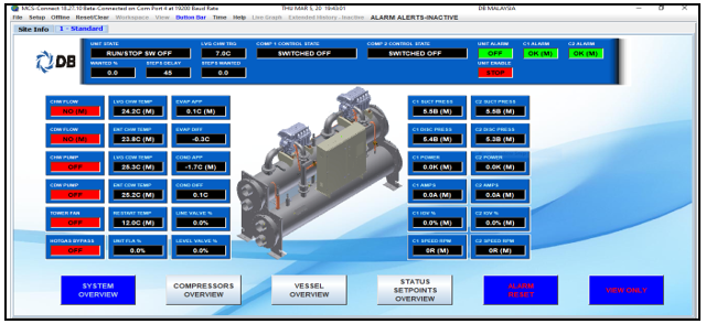
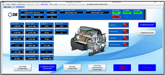
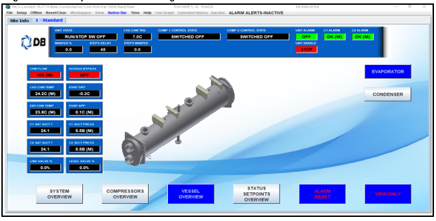
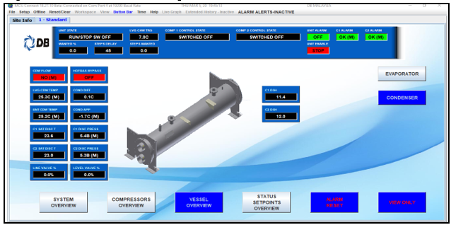
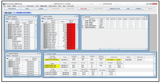
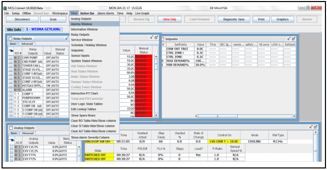
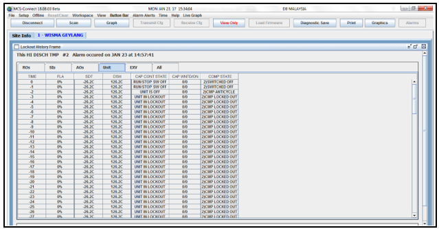
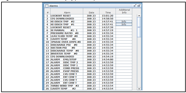
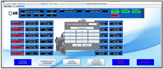
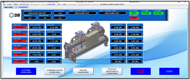
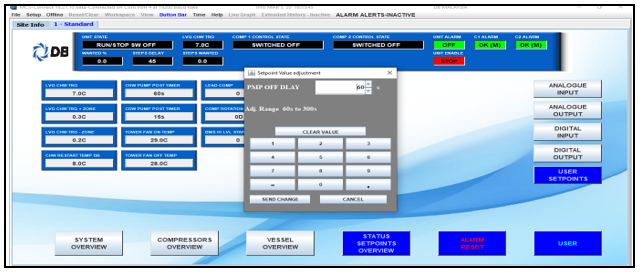
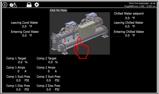
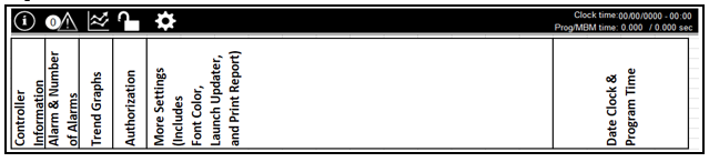
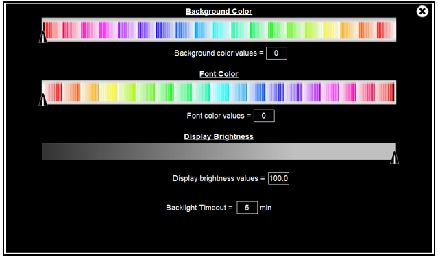
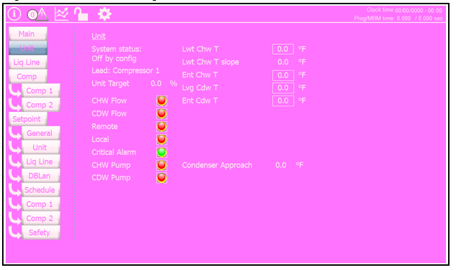
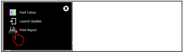
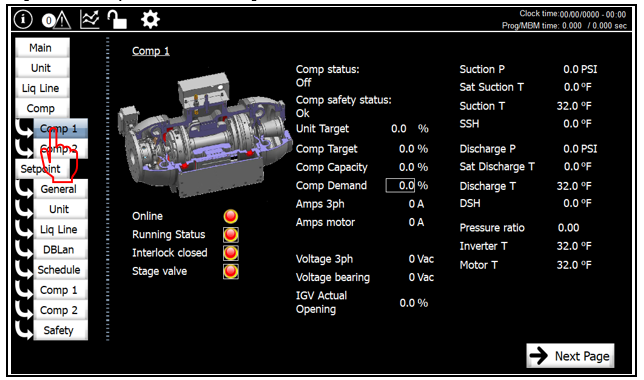
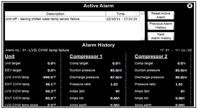
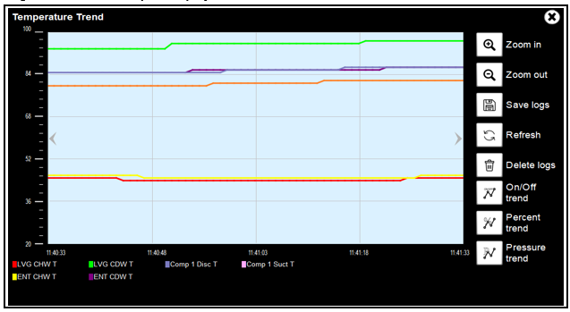
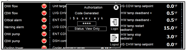
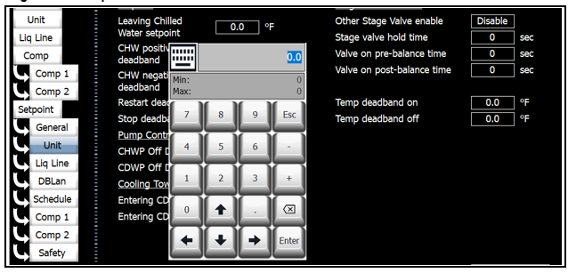
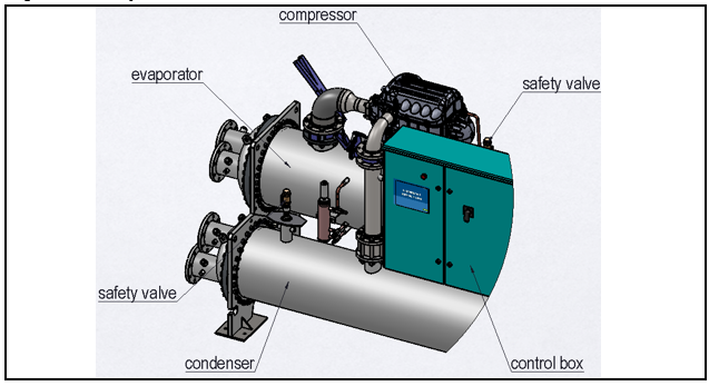
9.0 CONTROL SYSTEM 9.4 CONTROL SYSTEM HMI OPERATION GUIDE (GENERAL AIRSTAGE DIRECTOR) 9.4.1 System Overview page When the system is powered, the system overview page (Figure 9.4.1) appears. Figure 9.4.1 System Overview Page As shown in Figure 9.4.1, top of the page indicates the unit status, which includes “Unit in Power Up”, “Unit in Lockout”, “Unit is Off”, “Unit is Holding”, ”Unit is Unloaded”, “Unit is Loaded”, “Run/Stop SW Off” and etc. All the temperatures and pressures reading is showed on the system overview page. Also the compressor status, alarm status and run/stop switch status. There are few buttons at the bottom of the system page. Individual page can be shown by pressing the corresponding button. Go back to the system overview page by pressing the “System Overview” button. 9.4.2 Compressor Overview Page In compressor overview page (see Figure 9.4.2) each of the individual compressor’s main parameters on be viewed. Figure 9.4.2 Compressor Overview Page 9.0 CONTROL SYSTEM 9.4.3 Vessel Overview Page Pressed the "Vessel Overview" button to view for Evaporator and Condenser pages. Both evaporator and condenser parameters can be viewed in individual page. Figure 9.4.3A Evaporator Overview Page Figure 9.4.3B Condenser Overview Page 9.4.4 Status page Pressed the “Status” button and user can see all the readings from the sensors and all the parameter as showed as Figure 9.4.4. 9.0 CONTROL SYSTEM Figure 9.4.4 Status Page Illustration from the source manual omitted because Freshdesk does not support Base64-embedded images. 9.4.5 Alarm Page Pressed “View” button and followed by “Alarms Window” showed as Figure 9.4.5A, alarm window will pop up as showed as Figure 9.4.5B. It can store up to total of 99 alarms. Scroll “Up” and “Down” to check the alarm, and beside the alarm, there is an “info” button, user may pressed the info to get more details where it will record all the parameters before the unit/compressor trip. It is easier the user to troubleshoot the roots of the compressor tripped. Figure 9.4.5A Alarm Display 9.0 CONTROL SYSTEM Figure 9.4.5A Alarm Window Display Figure 9.4.5B Alarm Window Display (Continue) 9.4.6 Setpoint Modification To modify the setpoint, user must obtain at least the “User” authorization, pressed “View Only” button and it will pop up a keypad to ask user to enter the authorization code as Figure 9.4.6A. Enter user’s password “2020” and pressed “Enter”. The authorization will change from “View only” to “User” as Figure 9.4.6B and the color of the “CHW OUT TRG” changed from blue to grey color in the “system overview” page. Pressed on the “CHW OUT TRG” button , a keypad will pop up to let user to change the setpoint as Figure 9.4.6C, pressed enter key once the user has key in the desired control temperature setpoint. 9.0 CONTROL SYSTEM Figure 9.4.6A Enter Authorization Code Figure 9.4.6B User Authorization Figure 9.4.6C Setpoint Modification 9.0 CONTROL SYSTEM 9.5 CONTROL SYSTEM HMI OPERATION GUIDE (VISION) 9.5.1 Main page When the system is powered, the system overview page (Figure 9.5.1) appears. The main graphic shows all information in one page. It is using scroll menu features to explore the unit parameter. Figure 9.5.1 Main Page As shown in Figure 9.5.1. The graphic divided into three columns. Table 1, show for digital parameter which contain of digital input (red and green light referring to open and close signal input respectively) and digital output (red and green light referring to OFF and ON relay output respectively). Table 2, show for analog parameter which consist of percentage, temperature, pressure and others. While Table 3, show for setpoint parameter include the analog parameter that show in Table 2. 9.5.2 Menu Button On top of the graphic, there have seven buttons with different symbols. See Figure 9.5.2 for meaning of the symbols. Figure 9.5.2 Menu Button 9.0 CONTROL SYSTEM 9.5.3 Screen Color & Brightness The screen background and font color can be changed according to the user's convenience. Screen brightness and backlight timeout can also be adjusted as well. Figure 9.5.3A Screen Color & Brightness Figure 9.5.3B Screen Color & Brightness 9.0 CONTROL SYSTEM 9.5.4 Print Report The display can print a report with the immediate setpoints & reading of the chiller on the report. To do so, insert a USB pen drive into the display, and click on the ‘More Settings’ icon and click on ‘Print Report’. The number on the icon will change from 0 to 100, with 100 meaning the report is complete. The report will be in a .pdf format and is readily accessible on your computer. Figure 9.5.4 Status Page 9.5.5 Compressor Overview The compressor reading can be accessed by pressing on the ‘Comp 1’ button at the leftmost column. On this page, you will be able to access data on compressor capacity, pressure, temperature, speed, voltage, current, power, and number of cycles, alarm trips, run hours, and lockouts. Figure 9.5.5 Compressor Overview Page 9.0 CONTROL SYSTEM 9.5.6 Alarm The graphic offer alarm diagnosis and capture important parameter during alarm trigger. The alarm history can store up to 100 previous alarms. Figure 9.5.6 Alarm Window Display 9.5.7 Trend Graphs The graphic offer trend graph history such as temperature, pressure & percentage. Figure 9.5.7 Trend Graphs Display 9.0 CONTROL SYSTEM 9.5.8 Authorization There have three level of authorization which are user, technician and factory. The user and technician used fix password while factory level used dynamic password. The dynamic password is generate from code generated by controller. Figure 9.5.8 Authorization Login 9.5.9 Setpoint Modification To modify the setpoint, user must obtain at least the “User” authorization. The parameter reading with frame mean active touch button. Once user get authorize, user can modify the setpoint by touch the value. Figure 9.5.9 Setpoint Modification 10.0 PREPARATION BEFORE STARTUP 10.1 JOB DATA REQUIRED This Manual wiring diagrams Diagram and instructions for special control or options 10.2 TOOLS REQUIRED Mechanic’s tools (Refrigeration) Multi-meter Clamp on ammeter (For 380V Motor) Electronic leak detector. 10.3 CHECK CHILLER TIGHTNESS TEST PROCEDURE Leaking test was completed before leaving factory. The vessels will have enough refrigerant charge. Visual inspection, if there is no obvious leak, boot debugging judging whether quantity of refrigerant is enough. 10.4 INSPECT WATER PIPING Refer to piping diagrams provided in the certified drawings, and the piping instructions in the DCLC-M Installation Instructions manual. Inspect the piping to the evaporator and condenser. Be sure that flow directions are correct and that all piping specifications have been met. Make sure all valves are open in the water system. Inspect the cooling tower. Be sure it works properly. Water must be within design limits, clean, and treated to ensure proper chiller performance. 10.5 CHECK SAFETY VALVES Inspect safety valves according to 2.2.5.2. Safety valves locates as shown in Figure 10.5 on the machine. Figure 10.5 Safety Valve Position Safety valves are designed to protect the system from danger caused by over pressure. Safety valves must be in good condition in order to make sure that there is no hazard that would result in equipment damage and personal injury. 10.0 PREPARATION BEFORE STARTUP 10.6 CHECK THE SERVICE VALVE Compressor suction & discharge service valves are optional items, if equipped with these service valve (as shown in Figure 10.6), before starting, must check these valves, ensure in the fully open position. Figure 10.6 Check Valve Position 10.7 INSPECT WIRING User must not check the power supply until no danger is declared by qualified electrical engineer. Otherwise it will cause serious injury. Identify control cabinet and compressor I/O board, all the terminals has been tightened. Check whether the control box is grounding. Grounding resistance is in accordance with the relevant specification. Do not apply any kind of test voltage, even for a rotation check, if the chiller is under a dehydration vacuum. Insulation breakdown and serious damage may result. Examine wiring for conformance to job wiring diagrams and to all applicable electrical codes. On low-voltage compressors (600V or less) connect voltmeter across the power wires to the compressor starter and measure the voltage. Compare this reading with the voltage rating on the compressor and starter nameplates. Make sure that the customer’s contractor has verified proper operation of the pumps, cooling tower fans, and associated auxiliary equipment. This includes ensuring that motors are properly lubricated and have proper electrical supply and proper rotation. 11.0 INITIAL STARTUP 11.1 PREPARATION BEFORE STARTUP Power is on to the cooling tower fan starter, water pump box, and the magnetic control box. Cooling tower water is at proper level and at or below design entering temperature. Chiller is charged with refrigerant and all refrigerant and oil valves are in their proper operating position. Valves in the evaporator, condenser and cooling tower water circuits are open. 12.0 OPERATION GUIDE 12.1 OPERATOR DUTIES Operators must be properly trained and get authorization from GENERAL AIRSTAGE to work on the chillers, and become familiar with refrigeration chiller and related equipment before operating the chiller. Prepare the system for start-up, start and stop the chiller. Maintain a log of operating conditions and document any abnormal readings. Inspect and maintain the equipment, and make routine check points. Protect the system from any damage during shutdown periods. Do not change the set points, time schedules, and control logic functions. 12.2 CHILLER START, RUN & STOP 12.2.1 Start The Water Pumps. 12.2.2 Start The Chiller. 12.2.3 After the compressor starts at least 30 minutes, the operator should monitor the HMI display and observe the parameters for normal operating conditions. If any alarm, must investigate and determine the cause of fault. Evaporator pressures should within normal range according to their corresponding temperatures. If appear low suction pressure alarm and shutdown, need to find out the cause of the problem. Condenser pressures should within normal range according to their corresponding temperatures. If appear high discharge pressure alarm and shutdown, need to find out the cause of the problem. 12.2.4 Stop The Chiller And Extended Shutdown Frequent starts should avoid. The compressor will shut down when change the R/O/L switch to position “O” or press the emergency button on the control panel if any emergency case occurs. After the chiller stopped, the chilled water pump will stop, followed by condenser water pump. During extended shutdown, the refrigerant should be transferred into the pump out storage tank. Maintain a holding charge of 30~70PSI of refrigerant to prevent air from leaking into the chiller. If freezing temperatures are likely to occur in the chiller area, drain the chilled water, condenser water, and the pump out condenser water circuits to avoid freeze-up. Keep the water box drains open. Check the leakage of chiller during extended shutdown. It may be advisable to flush the water circuits to remove any soft rust which may have formed. 13.0 MAINTENANCE 13.1 PREVENTATIVE MAINTENANCE It is the responsibility of the owner to provide the necessary daily, monthly and yearly maintenance requirements of the system. In any operating system, it is most important to provide a planned maintenance and inspection of its functioning parts to keep it operating at its peak efficiency. Therefore, the following maintenance should be performed when prescribed. NOTE: If a unit failure occurs due to improper maintenance during the warranty period: GENERAL AIRSTAGE will not be liable for costs incurred to return the system to satisfactory operation. Electrical Isolation Isolate electrical power supply to the chiller from the facility. Isolate plant fluid flow to the chiller at appropriate valves or have refrigerant isolated to prevent freewheeling the driveline and generating electrical energy from the permanent magnet rotor. Table 13.1 Maintenance Requirements | Tasks | Daily | Monthly | Half-Yearly | Yearly | Bi-Yearly | | Monitor and record chiller’s operating parameters in log sheet. | × | | | | | | Download and analyze compressor fault log. | | | | | × | | Check operation of compressor IGV assembly. | | | | × | | | Check DC Bus Voltage (Compressor). | | | | × | | | Check for proper refrigerant levels. | | × | | | | | Carry out refrigerant leak test with a halide torch or an electronic leak detector. | | | | × | | | Check liquid line sight glass for sign of excessive moisture content and filter drier for sign of excessive pressure drop. Replace filter drier as necessary.(1) | | | | × | | | Verify evaporator and condenser liquid flow, and check flow switch operation. | | × | | | | | Water analysis to verify that both the water loop are properly treated.(2) | | | | | × | | Review operating data for signs of increased power consumption. | | | | × | | | Evaporator and condenser tube cleaning.(3) | | | | × | | | Check for proper concentration of antifreeze solution, if applicable. | | | | × | | | Perform Eddy Current testing and inspect tubes.(4) | | | | | | | Check strainer, clean as necessary. | | | | × | | | Check for any loose mechanical valves and parts, and tighten as necessary. | | × | | | | | Check for any loose cable termination and tighten as necessary. | | | | × | | | Check and verify accuracy of transducers, thermistor, etc., calibrate as necessary. | | × | | | | | Check Electronic Expansion Valve (EEV) operation. | | × | | | | | Check 3-phase voltage and current balance. | | × | | | | | Check signs of overheating / hot spot in electrical cables and components. | | | | | × | | Check programmable operating setpoints and safety cutouts. | | | | × | | | Check moisture, refer moisture prevention service bulletin. | | | × | | |
Notes: Replace filter if pressure different between inlet and outlet ends is more than 3PSID [0.21Bar]. More frequent water analysis may be needed for condenser water loop when it is an open loop system. Monthly water analysis is recommended. More frequent cleaning may be required depending on site operating conditions. To perform as required by performance. 14.0 TROUBLESHOOTING GUIDE Refer to table below (Table 14.0) if there are any abnormalities during the operation. Determine the causes and solve the problems as soon as possible to bring the machine back to normal condition. Please always contact GENERAL AIRSTAGE local office for assistance. Table 14.0 Chiller Troubleshooting | Malfunction | Cause | Solution | | Compressor cannot run | Power off (Interrupt) Overload VFD fault Communication protocol fault | Power on after check Determine the cause of overload Check and replace Check and adjust the terminal | | Unduly Low evaporating pressure | Insufficient chilled water flow Under load Supply expansion valve failure The heat exchange efficiency of tube become worse because of fouling and scaling Insufficient refrigerant | Check the chilled water circuit and ensure the water flow reach its rated value Check the auto restart/stop temperatures Check or replace the supply expansion valve Clean the tube Charge the refrigerant to required volume | | Unduly High condensing pressure | Insufficient cooling water flow The cooling capacity of cooling tower decreases High condenser load because of the high cooling water temperature Air mixed into refrigerant The heat exchange efficiency of tube become worse because of fouling and scaling | Check the cooling water circuit and ensure the water flow reach its rated value Inspect the cooling tower Clean the tube Replace the contaminated refrigerant Clean the tube | | Chilled water cut off | Insufficient chilled water flow | Check the chilled water pump and chilled water circuit, bring up the water flow to rated value | | Main motor overload | Phase voltage unbalanced Power supply voltage drop too much Insufficient cooling refrigerant supplied to main motor | Balance the power supply phase voltage Reduce the power supply voltage drop Check and clean the refrigerant filter, turn up refrigerant regulating valve | | High evaporating pressure | The temperature of chilled water increases due to unexpected load | Normal | | Low condensing pressure | Low inlet cooling water temperature Big cooling water volume Insufficient cooling capacity due to lack of the refrigerant in the cooler | No failure. But pay attention to the temperature difference between entering chilled and cooling water Check the pressure difference of cooling water inlet and outlet, and adjust it to rated value Recharge more refrigerant to the set volume | | Pressure inside the chiller decrease(increase) when stop | The refrigerant temperature is affected by room temperature | Normal | | Vibration increases | The vibration-absorbing rubber aging The impeller unbalanced Bearings worn-out The base is broken Main motor abnormal | Replace the vibration-absorbing rubber Check the impeller and do dynamic balance again, or consult factory Consult factory Repair the base Check the main motor, disassemble it if necessary | | Compressor surge | High condensing pressure Low condensing pressure | Refer to high condensing pressure section Refer to low condensing pressure section |
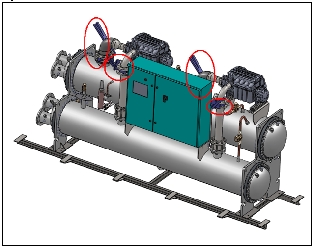
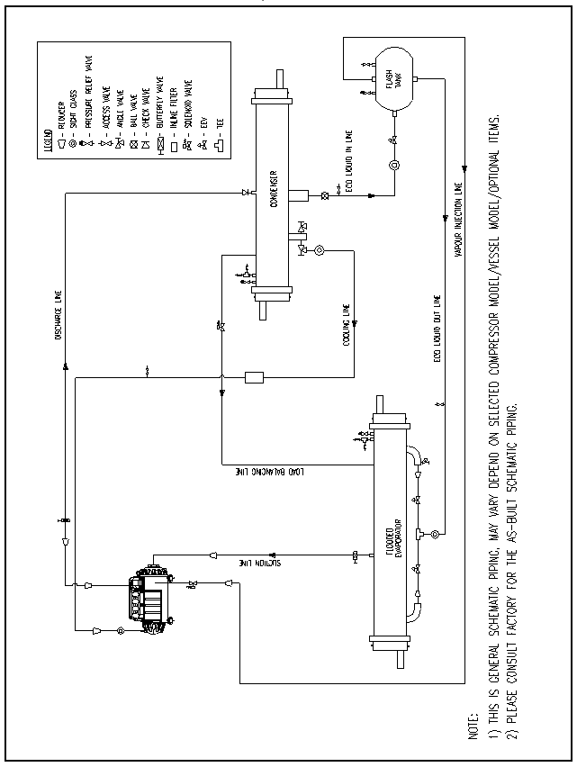
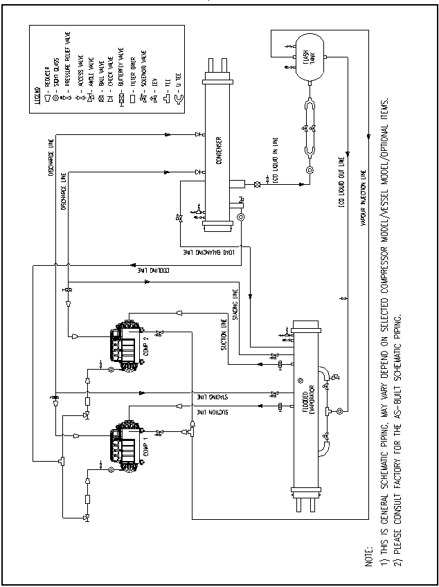
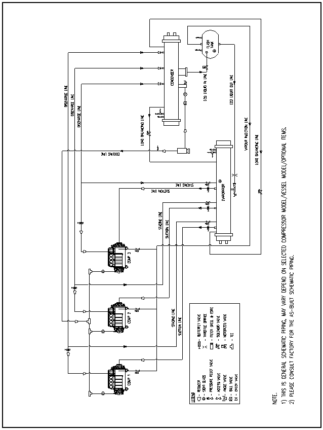
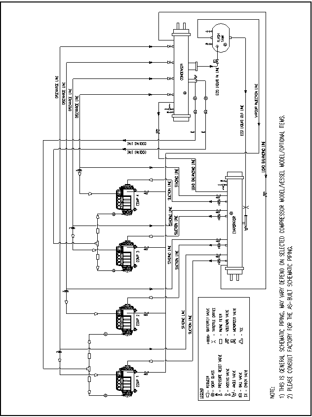
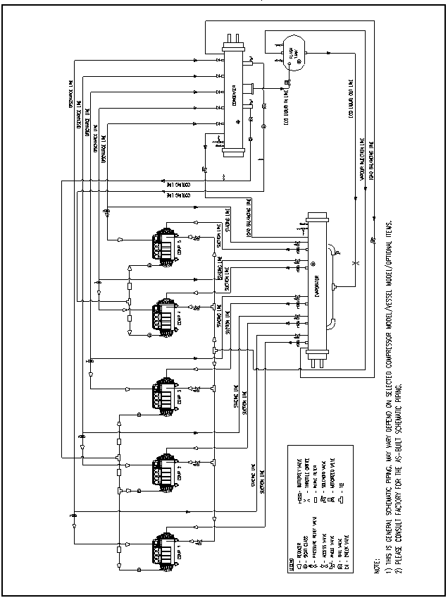
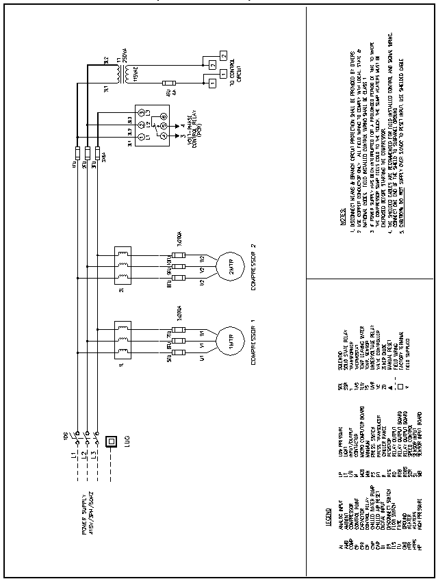
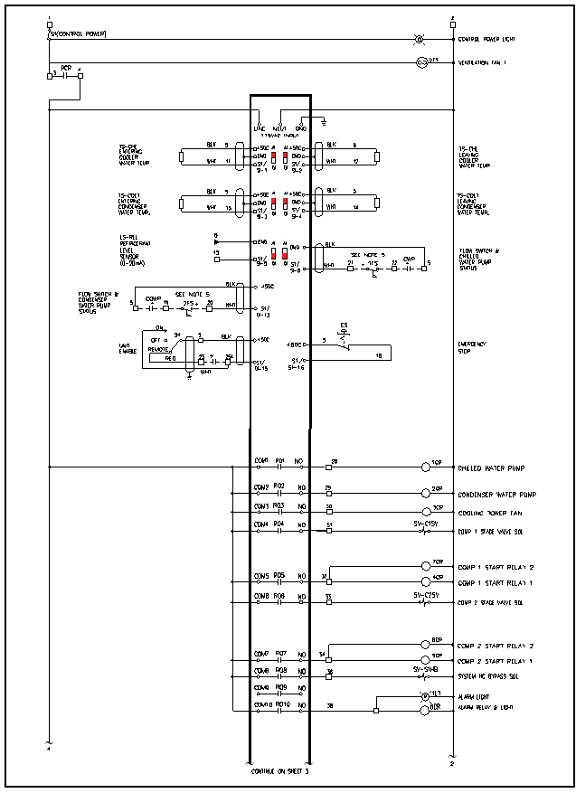
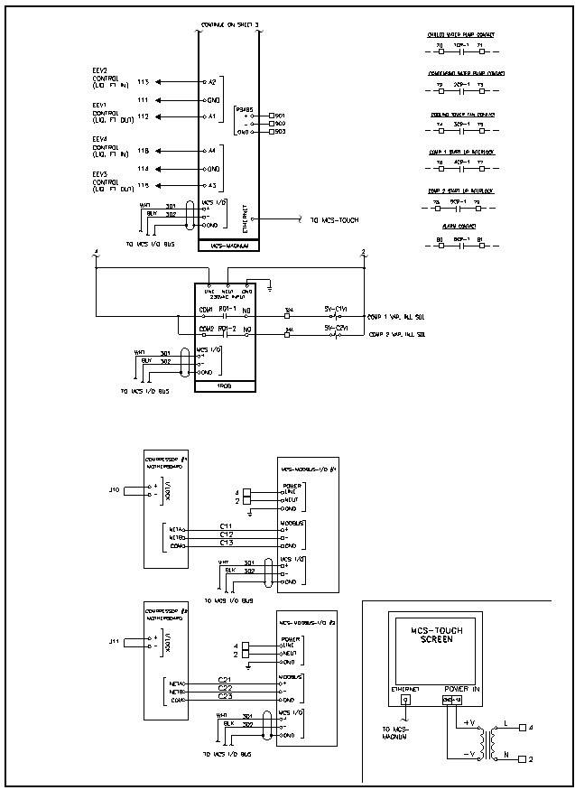
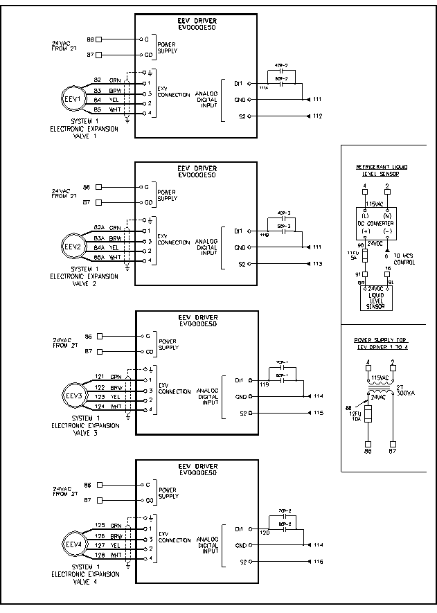
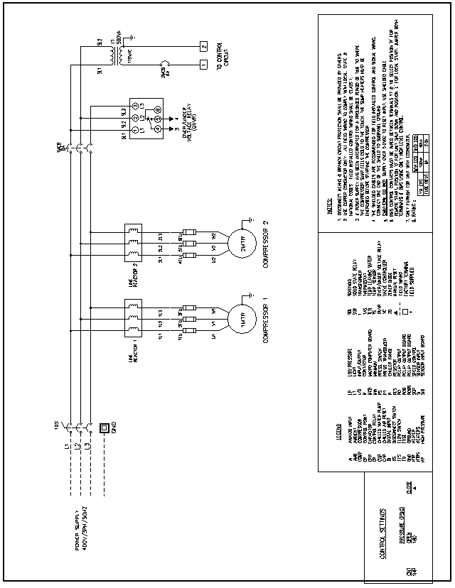
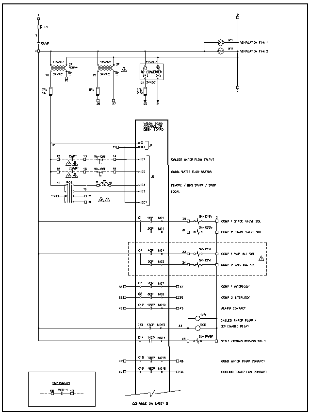
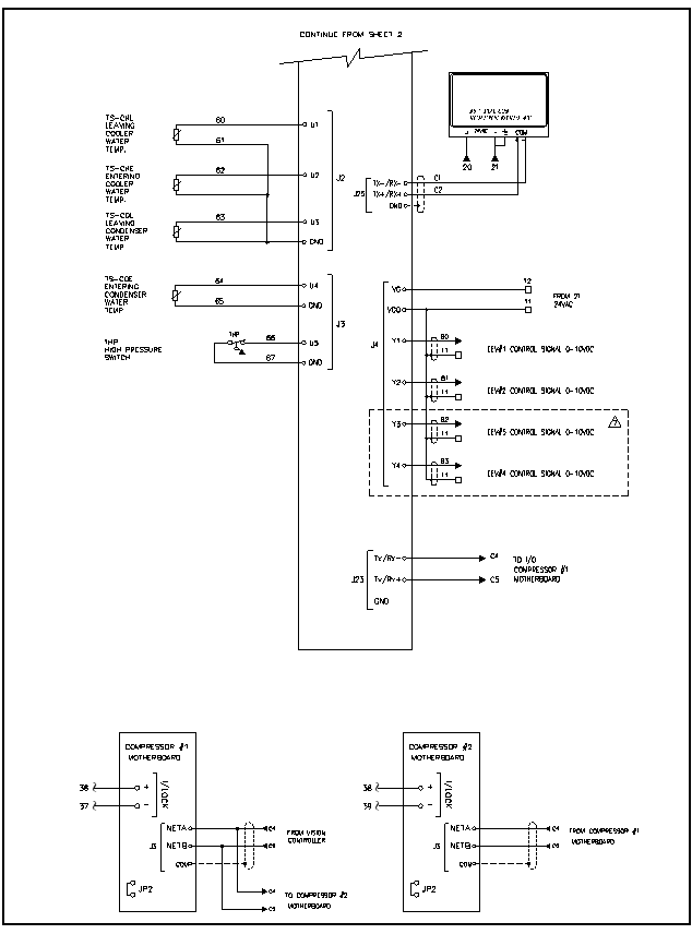
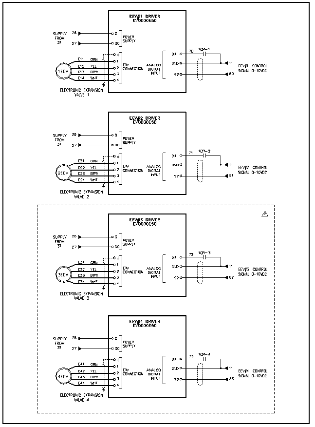
15.0 TYPICAL PIPING DIAGRAM 1 COMPRESSOR: TT300/ TT350, VESSEL: M2/ M3 15.0 TYPICAL PIPING DIAGRAM 2 COMPRESSORS: TT350/ TT400, VESSEL: M3/ M4 15.0 TYPICAL PIPING DIAGRAM 3 COMPRESSORS: TT400/ TT700/ TT400+TT700, VESSEL: M5/ M6/ M7 15.0 TYPICAL PIPING DIAGRAM 4 COMPRESSORS: TT700/ TT400+TT700, VESSEL: M7/ M8 15.0 TYPICAL PIPING DIAGRAM 5 COMPRESSORS: TT700 / TT400+TT700, VESSEL: M8 16.0 TYPICAL WIRING DIAGRAM 2 COMPRESSORS UNIT (GENERAL AIRSTAGE DIRECTOR) 16.0 TYPICAL WIRING DIAGRAM 16.0 TYPICAL WIRING DIAGRAM 16.0 TYPICAL WIRING DIAGRAM 16.0 TYPICAL WIRING DIAGRAM 2 COMPRESSORS UNIT (VISION) 16.0 TYPICAL WIRING DIAGRAM 16.0 TYPICAL WIRING DIAGRAM 16.0 TYPICAL WIRING DIAGRAM 17.0 APPENDIXES 17.1 CENTRIFUGAL CHILLER LOG SHEET | Date | | | | | | | | | | | | | | Time | | | | | | | | | | | | | | Total Operating Hours | | | | | | | | | | | | | | Chiller Room Temperature Dry Bulb/Wet Bulb | / | / | / | / | / | / | / | / | / | / | | | | Compressor | Discharge Temperature | | | | | | | | | | | | | IGV% Opening | | | | | | | | | | | | | Input Power | | | | | | | | | | | | | % Inverter FLA | | | | | | | | | | | | | % Motor FLA | | | | | | | | | | | | | DC Bus Voltage | | | | | | | | | | | | | Inverter Temperature | | | | | | | | | | | | | Motor Cavity Temperature | | | | | | | | | | | | | Evaporator | Refrigerant | Suction Pressure | | | | | | | | | | | | | Saturated Suction Temperature | | | | | | | | | | | | | Approach | | | | | | | | | | | | Water | Supply Temperature | | | | | | | | | | | | | Supply Pressure | | | | | | | | | | | | | Return Temperature | | | | | | | | | | | | | Return Pressure | | | | | | | | | | | | | Flow Rate | | | | | | | | | | | | Condenser | Refrigerant | Suction Pressure | | | | | | | | | | | | | Saturated Suction Temperature | | | | | | | | | | | | | Approach | | | | | | | | | | | | Water | Supply Temperature | | | | | | | | | | | | | Supply Pressure | | | | | | | | | | | | | Return Temperature | | | | | | | | | | | | | Return Pressure | | | | | | | | | | | | | Flow Rate | | | | | | | | | | |
17.0 APPENDIXES 17.2 SIGNALS FOR TEMPERATURE SENSOR (GENERAL AIRSTAGE DIRECTOR) Part Number: 4030007186 Description: TMP SEN MCS-T100-20 Range: -40°F – 248°F | Measure Temp (°F / °C) | Resistance (ohms) | Signal (Vdc) | Measure Temp (°F / °C) | Resistance (ohms) | Signal (Vdc) | | -40/-40 | 4015500 | 0.121 | 105/40.5 | 49846 | 3.337 | | -35/-37.2 | 3324096 | 0.146 | 110/43.3 | 44287 | 3.465 | | -30/-34.4 | 2760524 | 0.175 | 115/46.1 | 39420 | 3.586 | | -25/-31.6 | 2299670 | 0.208 | 120/48.8 | 35149 | 3.370 | | -20/-28.9 | 1921640 | 0.247 | 125/51.6 | 31399 | 3.805 | | -15/-26.1 | 1610592 | 0.292 | 130/54.4 | 28093 | 3.903 | | -10/-23.3 | 1353866 | 0.344 | 135/57.2 | 25173 | 3.994 | | -5/-20.6 | 1141345 | 0.403 | 140/60.0 | 22590 | 4.079 | | 0/-17.7 | 964963 | 0.470 | 145/62.8 | 20309 | 4.156 | | 5/-15.0 | 818070 | 0.545 | 150/65.5 | 18284 | 4.227 | | 10/-12.2 | 695433 | 0.629 | 155/68.3 | 16484 | 4.292 | | 15/-9.4 | 592755 | 0.722 | 160/71.1 | 14881 | 4.352 | | 20/-6.6 | 506560 | 0.824 | 165/73.8 | 13456 | 4.407 | | 25/-3.8 | 434007 | 0.936 | 170/76.6 | 12185 | 4.457 | | 30/-1.1 | 372778 | 1.058 | 175/79.4 | 11052 | 4.502 | | 32/0 | 351020 | 1.109 | 180/82.2 | 10033 | 4.544 | | 35/1.6 | 320976 | 1.188 | 185/85.0 | 9121 | 4.582 | | 40/4.4 | 277040 | 1.326 | 190/87.7 | 8303 | 4.617 | | 45/7.2 | 239686 | 1.472 | 195/90.5 | 7567 | 4.648 | | 50/10.0 | 207850 | 1.624 | 200/93.3 | 6906 | 4.677 | | 55/12.7 | 180647 | 1.782 | 205/96.1 | 6310 | 4.703 | | 60/15.5 | 157353 | 1.943 | 210/98.8 | 5773 | 4.727 | | 65/18.3 | 137363 | 2.106 | 215/101.6 | 5289 | 4.749 | | 70/21.1 | 120169 | 2.271 | 220/104.4 | 4849 | 4.769 | | 75/23.9 | 105347 | 2.435 | 225/107.2 | 4449 | 4.787 | | 80/26.7 | 92541 | 2.597 | 230/110.0 | 4085 | 4.804 | | 85/29.4 | 81454 | 2.756 | 235/112.7 | 3760 | 4.819 | | 90/32.2 | 71838 | 2.910 | 240/115.5 | 3463 | 4.833 | | 95/35.0 | 63480 | 3.058 | 245/118.3 | 3191 | 4.845 | | 100/37.7 | 56200 | 3.201 | 248/120 | 3040 | 4.852 |
17.0 APPENDIXES 17.3 SIGNALS FOR TEMPERATURE SENSOR (VISION) Part Number: 4030007700 (WH, WF & HP Type) Description: TMP SEN 6M NTC060WF-50-105C UL Range: -58 to 221oF | Temperature | Resistance Value (kΩ) | Temperature | Resistance Value (kΩ) | Temperature | Resistance Value (kΩ) | | | | | | | | | | | oC | oF | Max. | Typical | Min. | oC | oF | Max. | Typical | Min. | oC | oF | Max. | Typical | Min. | | -50 | -58.0 | 344.60 | 329.50 | 314.90 | 1 | 33.8 | 26.65 | 26.13 | 25.62 | 56 | 132.8 | 3.50 | 3.43 | 3.35 | | -49 | -56.2 | 325.00 | 310.90 | 297.30 | 2 | 35.6 | 25.52 | 25.03 | 24.55 | 57 | 134.6 | 3.39 | 3.32 | 3.25 | | -48 | -54.4 | 306.60 | 293.50 | 280.90 | 3 | 37.4 | 24.44 | 23.99 | 23.54 | 58 | 136.4 | 3.28 | 3.22 | 3.15 | | -47 | -52.6 | 289.40 | 277.20 | 265.40 | 4 | 39.2 | 23.42 | 23.00 | 22.57 | 59 | 138.2 | 3.18 | 3.12 | 3.05 | | -46 | -50.8 | 273.40 | 262.00 | 251.00 | 5 | 41.0 | 22.45 | 22.05 | 21.66 | 60 | 140.0 | 3.09 | 3.02 | 2.95 | | -45 | -49.0 | 258.30 | 247.70 | 237.40 | 6 | 42.8 | 21.53 | 21.15 | 20.78 | 61 | 141.8 | 2.99 | 2.93 | 2.86 | | -44 | -47.2 | 244.20 | 234.30 | 224.70 | 7 | 44.6 | 20.64 | 20.30 | 19.95 | 62 | 143.6 | 2.90 | 2.84 | 2.77 | | -43 | -45.4 | 231.00 | 221.70 | 212.80 | 8 | 46.4 | 19.81 | 19.48 | 19.15 | 63 | 145.4 | 2.82 | 2.75 | 2.69 | | -42 | -43.6 | 218.60 | 209.90 | 201.60 | 9 | 48.2 | 19.01 | 18.70 | 19.39 | 64 | 147.2 | 2.73 | 2.67 | 2.61 | | -41 | -41.8 | 207.00 | 198.90 | 191.00 | 10 | 50.0 | 18.25 | 17.96 | 17.67 | 65 | 149.0 | 2.65 | 2.59 | 2.53 | | -40 | -40.0 | 196.00 | 188.50 | 181.10 | 11 | 51.8 | 17.51 | 17.24 | 16.97 | 66 | 150.8 | 2.57 | 2.51 | 2.45 | | -39 | -38.2 | 185.50 | 178.50 | 171.60 | 12 | 53.6 | 16.81 | 16.56 | 16.30 | 67 | 152.6 | 2.50 | 2.44 | 2.38 | | -38 | -36.4 | 175.60 | 169.00 | 162.60 | 13 | 55.4 | 16.14 | 15.90 | 15.67 | 68 | 154.4 | 2.42 | 2.36 | 2.31 | | -37 | -34.6 | 166.30 | 160.20 | 154.20 | 14 | 57.2 | 15.50 | 15.28 | 15.06 | 69 | 156.2 | 2.35 | 2.30 | 2.24 | | -36 | -32.8 | 157.60 | 151.90 | 146.30 | 15 | 59.0 | 14.89 | 14.69 | 14.48 | 70 | 158.0 | 2.28 | 2.23 | 2.17 | | -35 | -31.0 | 149.40 | 144.10 | 138.80 | 16 | 60.8 | 14.31 | 14.12 | 13.92 | 71 | 159.8 | 2.22 | 2.16 | 2.11 | | -34 | -29.2 | 141.70 | 136.70 | 131.80 | 17 | 62.6 | 13.75 | 13.58 | 13.39 | 72 | 161.6 | 2.15 | 2.10 | 2.05 | | -33 | -27.4 | 134.50 | 129.80 | 125.20 | 18 | 64.4 | 13.22 | 13.06 | 12.89 | 73 | 163.4 | 2.09 | 2.04 | 1.99 | | -32 | -25.6 | 127.70 | 123.30 | 119.00 | 19 | 66.2 | 12.72 | 12.56 | 12.40 | 74 | 165.2 | 2.03 | 1.98 | 1.93 | | -31 | -23.8 | 121.20 | 117.10 | 113.10 | 20 | 68.0 | 12.24 | 12.09 | 11.94 | 75 | 167.0 | 1.98 | 1.92 | 1.87 | | -30 | -22.0 | 115.20 | 111.30 | 107.50 | 21 | 69.8 | 11.77 | 11.63 | 11.50 | 76 | 168.8 | 1.92 | 1.87 | 1.82 | | -29 | -20.2 | 109.40 | 105.70 | 102.20 | 22 | 71.6 | 11.32 | 11.20 | 11.07 | 77 | 170.6 | 1.87 | 1.82 | 1.77 | | -28 | -18.4 | 103.90 | 100.50 | 97.20 | 23 | 73.4 | 10.90 | 10.78 | 10.66 | 78 | 172.4 | 1.81 | 1.77 | 1.72 | | -27 | -16.6 | 98.68 | 95.52 | 92.45 | 24 | 75.2 | 10.49 | 10.38 | 10.27 | 79 | 174.2 | 1.76 | 1.72 | 1.67 | | -26 | -14.8 | 93.80 | 90.84 | 87.97 | 25 | 77.0 | 10.10 | 10.00 | 9.90 | 80 | 176.0 | 1.72 | 1.67 | 1.62 | | -25 | -13.0 | 89.20 | 86.43 | 83.73 | 26 | 78.8 | 9.73 | 9.63 | 9.53 | 81 | 177.8 | 1.67 | 1.62 | 1.58 | | -24 | -11.2 | 84.85 | 82.26 | 79.74 | 27 | 80.6 | 9.38 | 9.28 | 9.18 | 82 | 179.6 | 1.62 | 1.58 | 1.53 | | -23 | -9.4 | 80.76 | 78.33 | 75.96 | 28 | 82.4 | 9.04 | 8.94 | 8.84 | 83 | 181.4 | 1.58 | 1.53 | 1.49 | | -22 | -7.6 | 76.89 | 74.61 | 72.39 | 29 | 84.2 | 8.72 | 8.62 | 8.52 | 84 | 183.2 | 1.54 | 1.49 | 1.45 | | -21 | -5.8 | 73.23 | 71.10 | 69.01 | 30 | 86.0 | 8.41 | 8.31 | 8.21 | 85 | 185.0 | 1.49 | 1.45 | 1.41 | | -20 | -4.0 | 69.77 | 67.77 | 65.82 | 31 | 87.8 | 8.11 | 8.01 | 7.92 | 86 | 186.8 | 1.45 | 1.41 | 1.37 | | -19 | -2.2 | 66.44 | 64.57 | 62.74 | 32 | 89.6 | 7.83 | 7.73 | 7.63 | 87 | 188.6 | 1.42 | 1.37 | 1.33 | | -18 | -0.4 | 63.30 | 61.54 | 59.83 | 33 | 91.4 | 7.55 | 7.45 | 7.36 | 88 | 190.4 | 1.38 | 1.34 | 1.30 | | -17 | 1.4 | 60.32 | 58.68 | 57.07 | 34 | 93.2 | 7.29 | 7.19 | 7.10 | 89 | 192.2 | 1.34 | 1.30 | 1.26 | | -16 | 3.2 | 57.51 | 55.97 | 54.46 | 35 | 95.0 | 7.04 | 6.94 | 6.85 | 90 | 194.0 | 1.31 | 1.27 | 1.23 | | -15 | 5.0 | 54.85 | 53.41 | 51.99 | 36 | 96.8 | 6.79 | 6.70 | 6.61 | 91 | 195.8 | 1.27 | 1.23 | 1.19 | | -14 | 6.8 | 52.33 | 50.98 | 49.65 | 37 | 98.6 | 6.56 | 6.47 | 6.37 | 92 | 197.6 | 1.24 | 1.20 | 1.16 | | -13 | 8.6 | 49.95 | 48.68 | 47.43 | 38 | 100.4 | 6.34 | 6.25 | 6.15 | 93 | 199.4 | 1.21 | 1.17 | 1.13 | | -12 | 10.4 | 47.69 | 46.50 | 45.32 | 39 | 102.2 | 6.12 | 6.03 | 5.94 | 94 | 201.2 | 1.17 | 1.14 | 1.10 | | -11 | 12.2 | 45.55 | 44.43 | 43.33 | 40 | 104.0 | 5.92 | 5.83 | 5.74 | 95 | 203.0 | 1.14 | 1.11 | 1.07 | | -10 | 14.0 | 43.52 | 42.47 | 41.43 | 41 | 105.8 | 5.72 | 5.63 | 5.54 | 96 | 204.8 | 1.12 | 1.08 | 1.04 | | -9 | 15.8 | 41.55 | 40.57 | 39.60 | 42 | 107.6 | 5.53 | 5.44 | 5.35 | 97 | 206.6 | 1.09 | 1.05 | 1.02 | | -8 | 17.6 | 39.69 | 38.77 | 37.86 | 43 | 109.4 | 5.34 | 5.26 | 5.17 | 98 | 208.4 | 1.06 | 1.02 | 0.99 | | -7 | 19.4 | 37.92 | 37.06 | 36.21 | 44 | 111.2 | 5.17 | 5.08 | 4.99 | 99 | 210.2 | 1.03 | 1.00 | 0.97 | | -6 | 21.2 | 36.25 | 35.44 | 34.64 | 45 | 113.0 | 5.00 | 4.91 | 4.83 | 100 | 212.0 | 1.01 | 0.97 | 0.94 | | -5 | 23.0 | 34.66 | 33.90 | 33.15 | 46 | 114.8 | 4.83 | 4.75 | 4.67 | 101 | 213.8 | 0.98 | 0.95 | 0.92 | | -4 | 24.8 | 33.15 | 32.44 | 31.73 | 47 | 116.6 | 4.68 | 4.59 | 4.51 | 102 | 215.6 | 0.96 | 0.92 | 0.89 | | -3 | 26.6 | 31.72 | 31.05 | 30.39 | 48 | 118.4 | 4.52 | 4.44 | 4.36 | 103 | 217.4 | 0.93 | 0.90 | 0.87 | | -2 | 28.4 | 30.36 | 29.73 | 29.11 | 49 | 120.2 | 4.38 | 4.30 | 4.22 | 104 | 219.2 | 0.91 | 0.88 | 0.85 | | -1 | 30.2 | 29.06 | 28.48 | 27.89 | 50 | 122.0 | 4.24 | 4.16 | 4.08 | 105 | 221.0 | 0.89 | 0.86 | 0.83 | | 0 | 32.0 | 27.83 | 27.28 | 26.74 | 51 | 123.8 | 4.10 | 4.03 | 3.95 | 106 | 222.8 | 0.87 | 0.84 | 0.81 | | 52 | 125.6 | 3.97 | 3.90 | 3.82 | 107 | 224.6 | 0.84 | 0.82 | 0.79 | | | | | | 53 | 127.4 | 3.85 | 3.77 | 3.70 | 108 | 226.4 | 0.82 | 0.80 | 0.77 | | | | | | 54 | 129.2 | 3.73 | 3.65 | 3.58 | 109 | 228.2 | 0.80 | 0.78 | 0.75 | | | | | | 55 | 131.0 | 3.61 | 3.54 | 3.46 | 110 | 230.0 | 0.79 | 0.76 | 0.73 | | | | |
17.0 APPENDIXES INSTALLATION CHECKLIST Model NO.: Series NO.: Project name: Contract NO.: Telephone: FAX: Project address: Agency name: Installation company name: The following work must be completed when install the chiller: GENERAL AIRSTAGE CHILLER Initial inspection Unit shipment checked to ensure all major components and shipping boxes arrived without any damages. NOTE: Any damage MUST be reported to the transportation company immediately for their inspection. All boxes and crates opened and inventoried with the packing list. NOTE: Any damage MUST be reported to GENERAL AIRSTAGE immediately for inspection. Component inspection: Compressor inspection: Compressor body. Transducer, wiring harnesses. Condenser/Evaporator shell components: Condenser/Evaporator relief valves. Condenser/Evaporator transducers. Condenser/Evaporator wiring harnesses. Condenser/Evaporator insulation. Condenser/Evaporator paint. Hot gas valve. Nitrogen pressure in vessels (If no refrigerant charged) Control panel components: User interface and display Internal wiring and components Any evidence of water infiltration Panel mounts and enclosure Unit assembled (if shipped dismantled) and refrigerant piping installed under GENERAL AIRSTAGE supervision. Vibration isolator mounts so that the unit is level, and isolators are equally deflected. 17.0 APPENDIXES WATER PIPING Condenser water piping is installed between condenser, pumps and cooling tower. Chilled water piping is installed between cooler, pumps, and cooling coils. Make-up and fill lines are installed to cooling tower and chilled water system. All water piping checked for strain – piping should not spring when connections are broken at unit. Water piping leak tested and flushed, and water strainers cleaned after flushing. Piping system filled with water and trapped air vented. Chilled and condenser water flow available to meet unit design requirements. REFRIGERANT RELIEF PIPING (when required) Refrigerant relief piping (with flexible connection) installed from unit to atmosphere (per local building code). ELECTRICAL WIRING Main Power Supply Main power supply available Wiring completed from main power supply to motor Control Centre: External control wiring completed from the control centre to chilled water flow switches. Power available and wiring completed to the following drives and motors, and rotation of each checked: Chilled and condenser water pump(s) Cooling tower fan TESTING, EVACUATION AND CHARGING (Under GENERAL AIRSTAGE Supervision if Unit Shipped Less Refrigerant or Dismantled) Dry Nitrogen available for testing. A high vacuum pump available for evacuation and dehydration of system. Refrigerant Unit (ready to be) (has been) pressure tested, evacuated, dehydrated and charged. CONDITIONS Cooling load available for testing and operating unit Personnel available for final wiring connections Personnel available for start-up and testing Owners operating personnel for instruction 17.0 APPENDIXES STARTUP CHECKLIST The following work must be completed before startup the chiller: GENERAL: Review the installation Checklist have been completed. Attach a completed copy for records. Water connection inlet and outlet are at proper locations, have hangers nearby that would support their weight and show to visible strain on chiller nozzles. Relief piping is complete and puts NO strain on the relief valves. Wiring is complete per wiring drawings and power feed terminations in the control panel are right. Confirm any field control wiring modifications are in accordance with wiring drawings. Verify the chiller is charged with refrigerant (pressures match refrigerant saturation for ambient temp). Verify evaporator pressure transducer isolation valve is open. Verify condenser pressure transducer isolation valve is open. Verify compressor suction isolation valve is open. Verify compressor discharge isolation valve is open. Verify liquid line isolation valve is open. Verify motor cooling angle valve is open. Verify electrical connections to motor are tight. Check the chiller for refrigerant leaks at joints. CONTROL PANEL Login at USER level access to ensure access to the necessary setpoints. Confirm all setpoints are suitable for the site conditions. CHILLER SYSTEM Evaluate cooler and condenser water flow indication compared to design information found on the sales order. If shell pressure drop is used, it should be within +/-15% of the rating information. Requirements to the device installation and other assistants: Representative of user signature: field management signature: DATE: DATE: |