
General Assist Technical Reference
Serial Communication Voltage Test
Terminal 2 (Neutral) to Terminal 3 (Signal)
This test confirms whether the DC serial communication signal is present between the indoor and outdoor units.
Quick Answer
| Test points | Terminal 2 (Neutral) to Terminal 3 (Signal) |
| Tool | Digital multimeter capable of AC/DC voltage measurement |
Expected Indoor Values
| Indoor Unit Family | Expected Voltage - Terminal 2 to 3 |
|---|---|
| AST & ART/C | 60-120 V |
| ASTA & ASTB | 40-90 V |
| ASTG | Approximately 200 V static |
| ARTG & 3-phase | Approximately 295 V static |
| ARTH | 50-250 V |
Expected Outdoor Values
| Outdoor Unit Family | Expected Voltage - Terminal 2 to 3 |
|---|---|
| AOTA | 60-120 V |
| AOTG | 3-110 V |
| AOTH | 3-110 V |
What is This Test?
This is a voltage test used to confirm that the DC serial communication signal exists between the indoor and outdoor unit.
Tools Required
- Digital multimeter capable of measuring AC and DC voltage
Procedure
- Disconnect the signal wire.
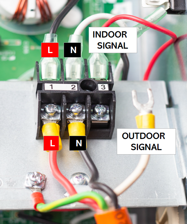
- Measure voltage between Terminal 2 (N) and Terminal 3 (Signal) at the indoor terminal block.
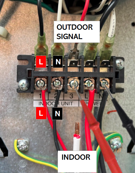
- Measure the same points at the outdoor terminal block.
- Record whether the voltage is stable, fluctuating, or absent.
Electrical safety: This test involves live electrical measurements. Only suitably qualified personnel should perform the test, using appropriate electrical safety procedures and test equipment.
Reference Images
Pass Criteria
The measured voltage is within the applicable range listed above for the indoor or outdoor unit family being tested.
If the Test Fails
| Result | Action |
|---|---|
| Indoor has signal, outdoor does not | Inspect and repair the signal wiring and terminations. Proceed to DC bus and supply-rail checks to rule out outdoor PCB resets. |
| Neither end has signal | Treat as a wiring or termination issue first. Confirm the correct terminals and repair or replace the interconnect if damaged. |
| Signal unstable / intermittent | Treat as a possible PCB reset or supply-rail collapse. Isolate loads using a staged reconnect test. |
Diagnostic note: Compare both ends of the communication circuit. The difference between the indoor and outdoor readings can help separate a wiring fault from a PCB or supply-related problem.