
General Assist Technical Procedure
VRF Outdoor Unit Test Run Procedure
Cooling and heating test operation from the outdoor unit PCB
Use this procedure during commissioning to verify installation, communication and system operation.
Purpose: The test run verifies correct installation, wiring, refrigerant charge and system operation before commissioning. It allows technicians to check cooling and heating performance, system communication and outdoor unit functionality.
Safety note: The system automatically stops test operation after 60 minutes. To stop manually or change between cooling and heating, use 02 - Test Run Stop first.
1. Preparation
Before starting the test run:
- Confirm the power supply is correctly connected and all indoor and outdoor units are energised.
- Ensure all addressing, whether manual or automatic, has been completed.
- Check that no error codes are displayed. LED102 must be OFF.
- Indoor units must be powered ON but switched OFF at their controllers.
- Ensure air filters and fan guards are fitted, and refrigerant piping and wiring are insulated and secured.
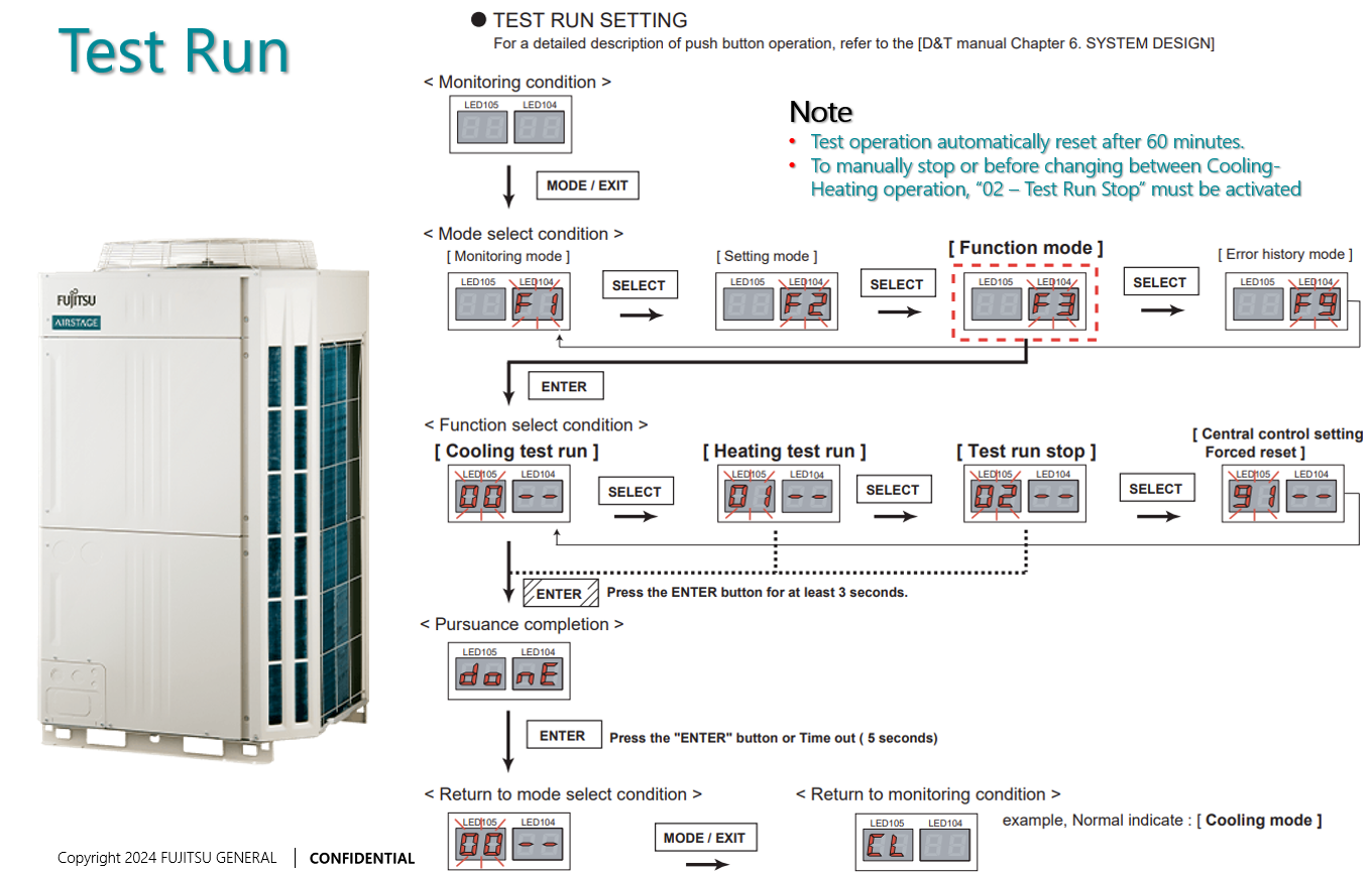
2. Outdoor unit PCB controls
The test run is started from the outdoor unit PCB using the following push-button switches and display indicators.
| Control | Function |
|---|---|
| SW107 | MODE/EXIT |
| SW108 | SELECT |
| SW109 | ENTER |
| LED105 / LED104 | 7-segment numeric display |
| LED101 - Green | Power ON indicator |
| LED102 - Red | Error indicator |
3. Test run procedure
Step 1 - Enter Function Mode
- Press MODE/EXIT (SW107) once.
Display: F1 - Press SELECT (SW108) once.
Display: F2 - Press ENTER (SW109) once to enter Function Mode Selection.
Step 2 - Select the test run function
Use SELECT (SW108) to cycle through the available options.
| Display | Function |
|---|---|
| 00 | Cooling Test Run |
| 01 | Heating Test Run |
| 02 | Test Run Stop |
| 03 | Central Control Forced Reset |
Step 3 - Start the test run
- When the required mode is displayed, press and hold ENTER (SW109) for at least 3 seconds. The display flashes to confirm the test has started.
- Observe the system and confirm:
- Outdoor fans and compressors start.
- Indoor fans and louvers operate.
- Refrigerant pressures and temperatures stabilise.
- The system continues test operation for up to 60 minutes unless manually stopped.
Step 4 - Stop or change the test mode
- Press SELECT (SW108) until 02 - Test Run Stop appears.
- Press and hold ENTER (SW109) for 3 seconds. The display confirms the stop with steady digits.
- To change from cooling to heating, or heating to cooling, always stop the current test before selecting the new mode.
4. Post-test confirmation
- Press MODE/EXIT (SW107) to return to Monitoring Mode. The display shows - - or an operation symbol: C for cooling or H for heating.
- Verify that no error LEDs are active, all indoor units respond to commands, and suction and discharge temperatures are within the design range.
- Record temperatures, pressures, amperage and refrigerant circuit address in the commissioning log.
5. Troubleshooting
| Issue | Possible cause | Corrective action |
|---|---|---|
| System fails to start | Indoor units not powered ON | Confirm the power supply and breaker status. |
| No compressor operation | Test Run Stop, 02, is still active | Re-enter Function Mode and restart the test. |
| LED102 is ON | Communication or wiring fault | Check X1/X2 transmission polarity. |
| System stops early | Automatic 60-minute timeout | Re-initiate the test if further evaluation is required. |
6. Important notes
- The test run is intended for functional verification, not full-load testing.
- Do not operate under extreme ambient conditions below 0°C or above 43°C.
- After completing the test, power cycle the system to clear temporary test settings.
Use the installation and service documentation applicable to the exact outdoor unit and VRF system series before commissioning or changing settings.