1. Purpose
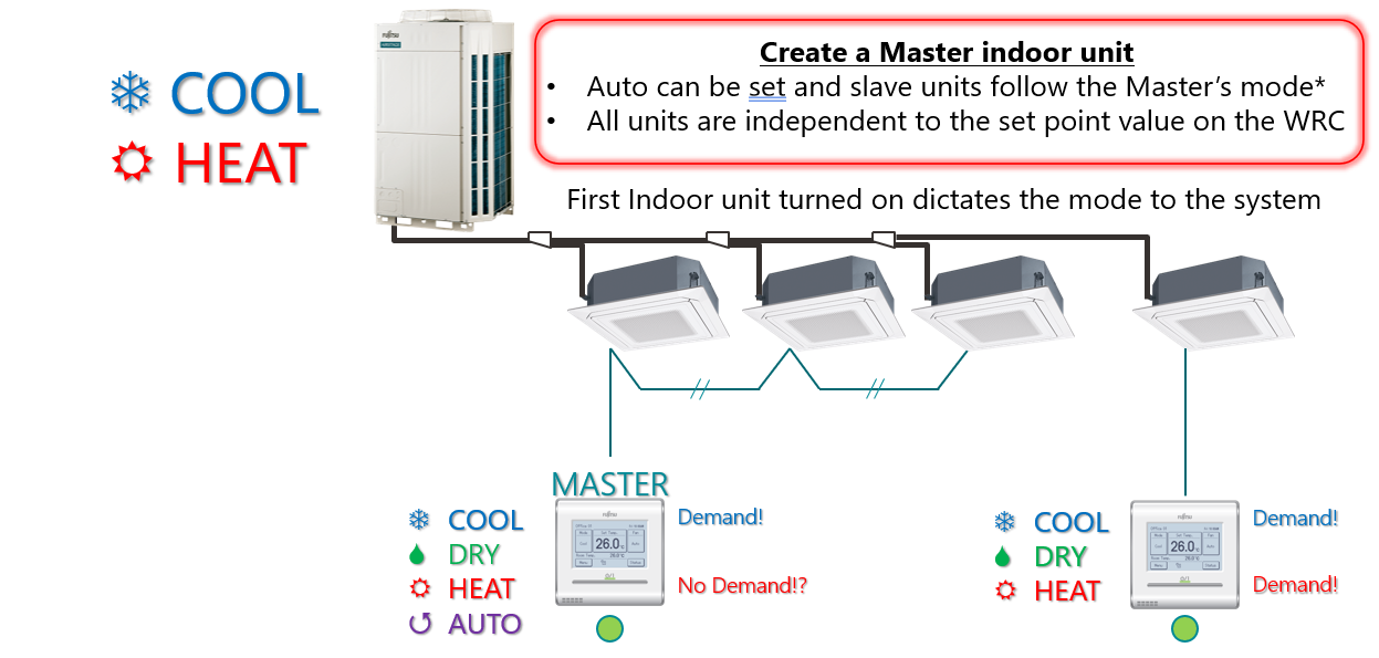
The Administrative Indoor Unit—commonly referred to as the Master Indoor Unit—controls the operation mode (Cool / Heat / Auto) for all connected indoor units in a 2-pipe system.
Once the Master is set, all slave indoor units will follow its operation mode, while each unit can still maintain an independent temperature setpoint.
Important:
The first indoor unit powered ON dictates the operation mode (Cool / Heat) for the entire system.
Master setup is mandatory before system commissioning.
2. Preparation
Before beginning the configuration:
Verify all indoor units and the outdoor unit are powered ON.
Confirm that the system has completed addressing (manual or automatic).
Ensure the communication wiring (X1 / X2) is correctly installed and polarity is maintained.
Confirm no active errors on the outdoor unit PCB (LED102 must be OFF, LED101 ON – green indicator light as
3. Step 1 – Set Administrative Function on the Outdoor Unit
Follow the steps below to register the system for administrative control (as illustrated on page 4 of the PDF 1740417761786_67bcaaddb921b
| Action | Button / Display |
|---|---|
| Press MODE/EXIT (SW107) once | Display: F1 |
| Press SELECT (SW108) once | Display: F2 |
| Press ENTER (SW109) once | Display: 00 00 |
| Press SELECT (SW108) eight times | Display: 21 00 |
| Press ENTER (SW109) once | Display: 21 00 confirmed |
| Press SELECT (SW108) two times | Display: 21 02 |
| Press ENTER (SW109) once | Display shows 21 02 (confirmed) |
| Press MODE/EXIT (SW107) three times | Display clears → Function saved |
This procedure activates Function F2-21-02, enabling administrative indoor unit operation for the connected system.

4. Step 2 – Set the Master Indoor Unit on the Remote Controller
Proceed using the touch-screen Wired Remote Controller (WRC). Refer to pages 5–6 of the PDF for screen visuals 1740417761786_67bcaaddb921b
Step-by-Step:
From the Monitor screen, press Menu.
On Main Menu Page 1, select Next Page.
On Main Menu Page 2, select Initial Setting.
On Initial Setting Page 1, press Next Page.
On Initial Setting Page 2, select Master Indoor Unit Setting.
When prompted, enter the Installer Password:
Factory default:
0000If changed, enter the new password.
The screen will display: “Not Master Indoor Unit” → press Set.
A confirmation message appears:
“The connected indoor unit will be set as the master indoor unit. OK?”
→ Press Yes to confirm.
The WRC will now register the selected indoor unit as the system’s Master Indoor Unit.

5. Verification
After setup:
The WRC display for the Master will show a “Master” indicator.
Slave units will automatically synchronize to the Master’s mode (COOL / HEAT / AUTO), though they can each maintain independent setpoints.
If multiple indoor units share the same refrigerant address, ensure only one Master is configured.
6. Notes for 2-Pipe Systems
Only one Master Indoor Unit can exist per refrigerant system.
All units connected to the same outdoor circuit will follow the Master’s operation mode.
Switching between COOL and HEAT modes must be initiated from the Master unit.
When a Master is active, any unit attempting to switch to the opposite mode will display “Operation restricted by Master.”
7. Function Settings for RB Units (Optional)
For multi-IU connections through an RB unit (page 3 of your images):
On the RB unit PCB, DIP switch SET2 positions 1–4 determine operation-mode priority and cool/heat control time.
Factory Default:
Priority to first command (SET2-1 = OFF, SET2-2 = OFF)
Cool/heat control time = 6 minutes (SET2-3 = OFF, SET2-4 = OFF)
If “Priority to Administrative Indoor Unit” is required, set SET2-1 = OFF, SET2-2 = ON.
8. Confirmation
Once complete:
Turn ON the Master indoor unit.
Confirm the system enters the desired mode (COOL or HEAT).
Verify all slave units respond accordingly.
Record the Master address and remote ID for commissioning documentation.
9. Troubleshooting
| Symptom | Possible Cause | Corrective Action |
|---|---|---|
| Cannot select Master | Outdoor Function F2-21-02 not enabled | Perform Step 1 on outdoor unit |
| Master not recognized by system | Addressing incomplete | Re-address indoor units and re-test |
| Slave units not following Master mode | Communication wiring fault or duplicate Masters | Verify X1/X2 network and Master assignment |
| Password rejected on WRC | Custom installer password set | Confirm correct code with administrator |
Summary
The Master Indoor Unit configuration establishes centralized mode control in a 2-pipe VRF network.
Sequence of setup:
Enable F2-21-02 on the Outdoor Unit PCB.
Designate the Master Indoor Unit using the Touch Screen WRC.
Confirm system mode synchronization and document the configuration.