
General Assist Technical Reference
Automatic Addressing
Precautions, wiring requirements and setup procedure
For VRF indoor units, RB units and signal amplifiers
Automatic addressing assigns communication addresses to compatible indoor units, RB units and signal amplifiers. It can simplify commissioning, but only when the system is correctly prepared, wired and isolated before the process begins.
Critical: Automatic addressing cannot be completed correctly when devices have already been manually addressed, multiple refrigerant systems are energised together, or signal amplifiers have not been addressed first.
1. Factory default address configuration
Before starting automatic addressing, confirm that all connected devices remain at their factory-default address settings.
| Component | Factory default | Requirement |
|---|---|---|
| Outdoor unit refrigerant address (REF AD) | 00 | Set the required refrigerant address manually at the outdoor unit before automatic addressing. |
| Indoor unit address (IU AD) | 00 | Do not manually change the address before automatic addressing. |
| RB unit address (RB AD) | 00 | Leave at the factory setting until the RB automatic-address process is performed. |
| Signal amplifier address | A1 | Where multiple amplifiers are installed, assign a unique address from A1 to A8 before addressing downstream devices. |
Do not mix manual and automatic addressing. A device that has already been manually addressed may not participate in the automatic-address process. Reset applicable addresses to factory default before retrying.
2. Wiring and system isolation
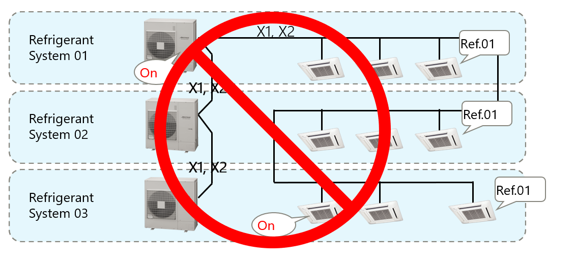
Incorrect arrangement - serial connection between refrigerant systems
DO NOT USE
| Refrigerant System 1 | → | Refrigerant System 2 | → | Refrigerant System 3 |
Serially linking separate refrigerant systems on the same transmission path can cause duplicate refrigerant addresses, cross-operation and incorrect outdoor-unit response.
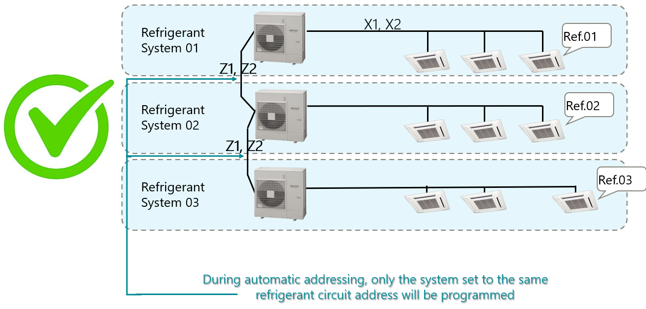
Correct arrangement - independent parallel branches
REQUIRED
| Refrigerant System 1 | Transmission line / network | Refrigerant System 2 |
Connect each refrigerant circuit as an independent parallel branch. During addressing, energise only the refrigerant system being addressed.
- Confirm all transmission cables are secure at the specified X1/X2 or Z1/Z2 terminals.
- Do not energise multiple refrigerant systems during automatic addressing.
- Confirm the communication path and any branch connections before proceeding.
- Correct any wiring or isolation issue before attempting to reset and re-address the system.
3. Required addressing sequence
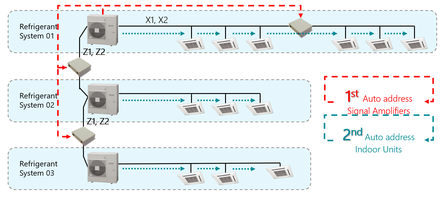
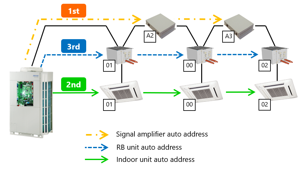
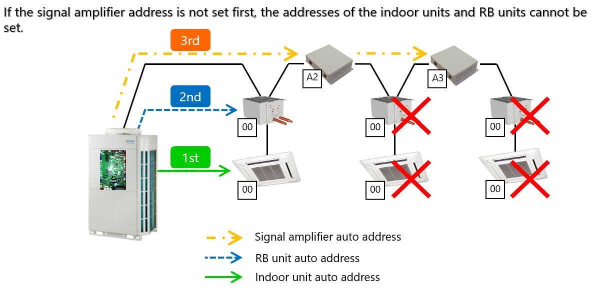
For systems that include signal amplifiers and RB units, complete addressing in the following order.
| Order | Component | Action |
|---|---|---|
| 1 | Signal amplifiers | Manually assign or verify unique amplifier addresses from A1 to A8. |
| 2 | Indoor units | Run indoor-unit automatic addressing and confirm that every connected indoor unit receives a unique address. |
| 3 | RB units | After indoor addressing is complete, run the RB-unit automatic-address process and verify detection. |
Why the sequence matters: If signal amplifiers are not addressed first, downstream indoor units and RB units may not register or may be assigned incorrectly.
4. Automatic addressing procedure
| 1 | Verify wiring | Check transmission cable connections, terminal selection and parallel branch layout. |
| 2 | Confirm default settings | Confirm applicable IU and RB addresses are set to 00, and signal-amplifier addresses are correctly assigned. |
| 3 | Set REF AD | Set the required outdoor-unit refrigerant address manually. |
| 4 | Isolate the system | Ensure only the refrigerant circuit being addressed is energised. |
| 5 | Start addressing | Initiate the required automatic-address function from the outdoor-unit PCB or approved service tool. |
| 6 | Wait and verify | Allow the process to finish. Confirm the detected device count and address status using the outdoor display or commissioning software. |
| 7 | Power cycle | After successful completion, switch the system off and back on so the assigned addresses are retained and communication can be rechecked. |
5. Common issues and corrective actions
| Issue | Likely cause | Corrective action |
|---|---|---|
| Indoor units are not recognised | Signal amplifier was not addressed first, or the communication path is incomplete. | Assign amplifier addresses, verify transmission wiring, reset affected addresses and repeat the sequence. |
| Duplicate addresses | More than one refrigerant system was powered during addressing. | Isolate all other refrigerant circuits, reset addresses as required and address one system at a time. |
| RB unit is not detected | Incorrect sequence, open circuit, loose connection or incorrect transmission wiring. | Complete indoor-unit addressing first, then inspect and test the RB communication path before retrying. |
| Communication error after addressing | Separate refrigerant systems have been serially connected, or an address conflict remains. | Correct the network to independent parallel branches, confirm address isolation and re-run addressing. |
| Addressing will not start | A device has a manual address or is outside the valid address range. | Return applicable devices to factory default and confirm that no IU or RB address is set from 64 to 99. |
6. Key technical notes
- The outdoor-unit refrigerant address must be set manually before automatic addressing.
- Automatic addressing should only be started after wiring, power isolation and address defaults have been verified.
- For multi-system networks, confirm refrigerant-system isolation before energising the next circuit.
- Do not use indoor-unit or RB-unit address values from 64 to 99.
- After any failed attempt, correct the underlying issue and reset affected addresses before repeating the process.
7. Pre-addressing checklist
✓ Indoor-unit and RB-unit addresses are at factory default.
✓ The outdoor-unit REF AD has been set manually.
✓ Refrigerant systems are connected as independent parallel branches.
✓ Signal amplifiers have unique addresses from A1 to A8.
✓ Only one refrigerant circuit is powered during addressing.
✓ The sequence will be completed in the order: signal amplifier, indoor units, then RB units.
Service note: The exact PCB switch operation and display codes vary by VRF model. Refer to the applicable installation or service manual before initiating the automatic-address function.