1. Purpose of RB Address Setting
The Refrigerant Branch (RB) Unit serves as the intermediate junction between the outdoor and indoor units in a VRF Heat Recovery System.
To ensure correct communication and refrigerant control:
The Refrigerant Circuit Address (REF AD) of the RB unit must match the outdoor and indoor units.
The RB Address (RB AD) must correspond to the indoor unit(s) connected downstream of it.
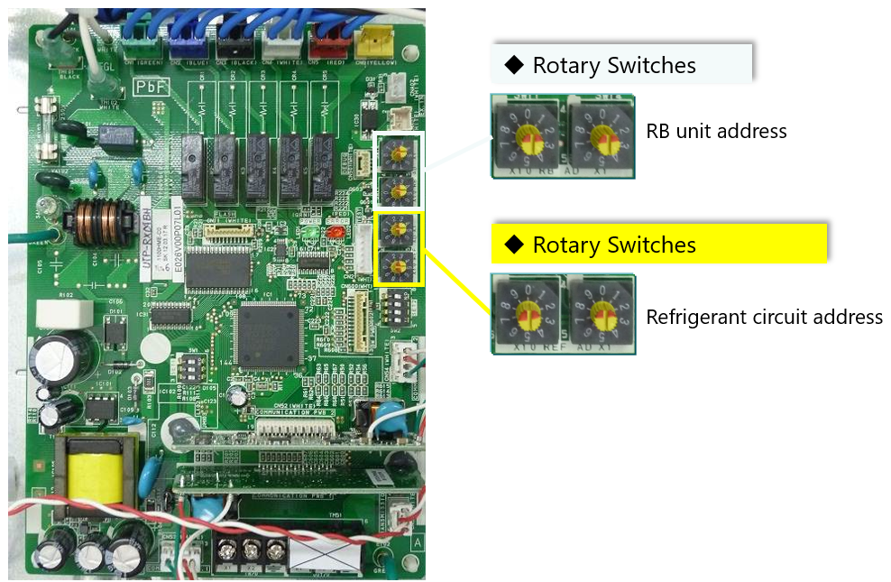
2. Location of Address Dials
On the RB Unit PCB, you will find two sets of rotary switches:
| Switch Type | Purpose | Label on PCB |
|---|---|---|
| REF AD (x10 / x1) | Refrigerant circuit address | SW606, SW607 |
| RB AD (x10 / x1) | RB unit address | SW604, SW605 |
The positions may differ slightly depending on the RB model (single or multi-port type), but the setting method is identical.
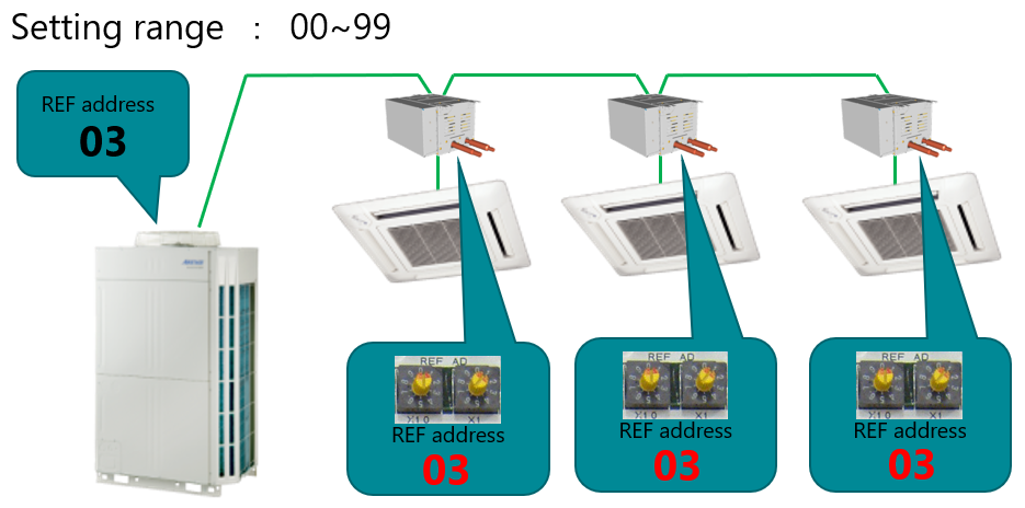
3. Step 1 – Set the Refrigerant Circuit Address (REF AD)
Each RB unit must share the same REF AD as the outdoor and indoor units within the same refrigerant circuit.
| Example | REF AD x10 | REF AD x1 |
|---|---|---|
| 03 | 0 | 3 |
| 11 | 1 | 1 |
| 25 | 2 | 5 |
Setting Range: 00 – 99
If the RB’s REF AD differs from the outdoor unit, the system will not operate.
4. Step 2 – Set the RB Unit Address (RB AD)
Each RB unit must be assigned a unique address within its refrigerant circuit to identify which indoor unit group it serves.
Procedure:
Locate the rotary switches marked RB AD x10 and RB AD x1.
Set each dial to the desired address number using the tables or diagrams.
Match the RB address to the Indoor Unit address of the connected zone.
| Example Configuration |
|:--|:--|
| REF AD = 03 (common for the system) | RB AD = same as corresponding IU AD |
| RB Unit | REF AD | RB AD | Connected IU AD |
|---|---|---|---|
| RB1 | 03 | 01 | 01 |
| RB2 | 03 | 02 | 02 |
| RB3 | 03 | 04 | 04 |
✅ Recommendation:
Set the RB AD to the same number as the Indoor Unit (IU AD) it serves.
This simplifies fault tracing and service verification.
5. Step 3 – Address Range and Restrictions
| Setting Type | Valid Range | Invalid Range | Remarks |
|---|---|---|---|
| REF AD | 00 – 99 | — | Must match Outdoor and IU |
| RB AD | 00 – 63 | 64 – 99 | 64–99 cannot communicate with the outdoor unit |
If an RB unit address is set between 64 and 99, communication failure will occur, and the system will not recognize that RB unit.
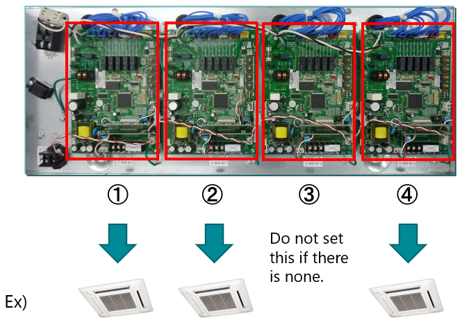
6. Step 4 – Multi-Port RB Unit Configuration
For multi-type RB units, each refrigerant control port has its own PCB (circuit board).
Set addresses individually for each active board (connected port).
| RB Port | Connection | Setting Requirement |
|---|---|---|
| ① | IU connected | Set REF AD and RB AD |
| ② | IU connected | Set REF AD and RB AD |
| ③ | No IU connected | Leave unset |
| ④ | IU connected | Set REF AD and RB AD |
Only configure ports that are connected to indoor units.
Blank ports do not require address assignment.
7. Step 5 – Verification
After setting all addresses:
Power ON the system.
Confirm communication via the indoor controller or commissioning tool.
Ensure that:
REF AD is identical across all units (OU, RB, IU).
RB AD matches the corresponding IU AD.
No duplicate RB addresses exist within the same refrigerant circuit.
8. Quick Reference Summary
| Component | Address Type | Setting Range | Relationship |
|---|---|---|---|
| Outdoor Unit | REF AD | 00–99 | Common across system |
| RB Unit | REF AD | 00–99 | Match Outdoor Unit |
| RB Unit | RB AD | 00–63 | Match connected IU AD |
| Indoor Unit | REF AD | 00–99 | Match Outdoor Unit |
| Indoor Unit | IU AD | 00–63 | Unique per IU |
9. Notes & Best Practices
Always confirm address positions before power-up to avoid bus communication errors.
When replacing RB PCBs, reapply the same address settings.
For multi-split or multi-branch systems, document all REF and RB addresses for service traceability.