
General Assist Technical Reference
VRF Outdoor Unit Addressing
REF address, master/slave configuration and outdoor unit quantity settings
Guide for configuring single, dual and triple outdoor unit refrigerant systems
Quick answer: Each refrigerant circuit needs one unique REF address. Outdoor units within the same refrigerant circuit use the same REF address, but each unit must have a different master/slave address. The total outdoor unit quantity must also be set on every outdoor unit.
Important: Isolate and confirm power is OFF before changing rotary or DIP switch settings. Do not use any switch combination identified as prohibited.
1. Preparation
Before addressing:
- Determine a clear addressing plan — e.g., by floor, zone, or refrigerant circuit.
- Confirm wiring is complete and correct between transmission cables and outdoor units (OUs).
- Ensure all OUs are powered OFF before adjustment.
2. Refrigerant Address Setting (REF AD)
Each refrigerant circuit requires a unique address (00–99) when multiple outdoor units are connected to the same communication line.
Procedure:
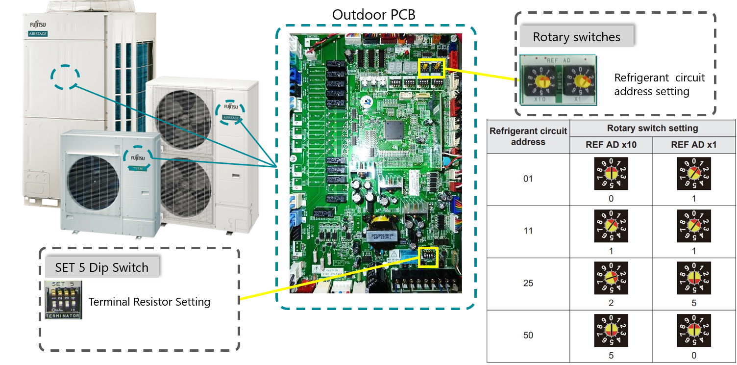
- Locate the Rotary Switches (REF AD x10 / REF AD x1) on the Outdoor PCB.
- Set the address using the following format:
- REF AD x10 sets the tens digit.
- REF AD x1 sets the ones digit.
- Example settings:
| Refrigerant Circuit Address | REF AD x10 | REF AD x1 |
|---|---|---|
| 01 | 0 | 1 |
| 11 | 1 | 1 |
| 25 | 2 | 5 |
| 50 | 5 | 0 |
Setting range: 00–99
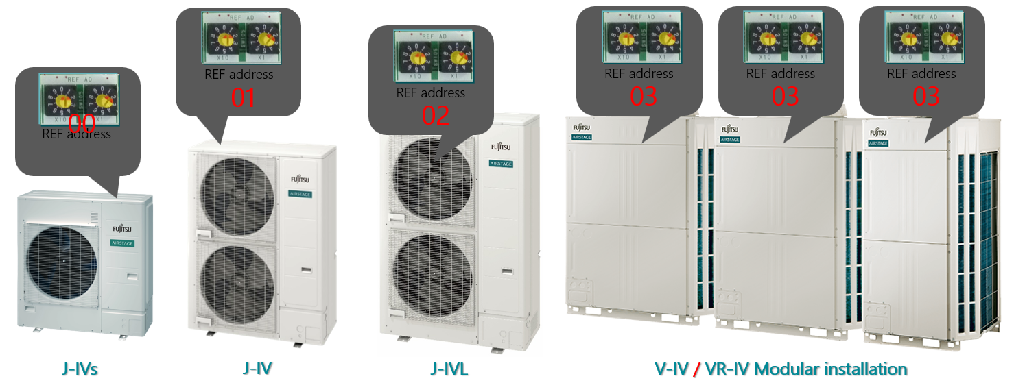
Each outdoor system (refrigerant circuit) must have a unique REF address.
3. Outdoor Unit Address Setting (SET3 Switch)
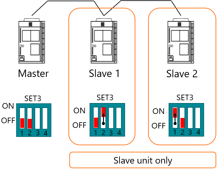
When multiple outdoor units are connected to one refrigerant system, each must have a unique Outdoor Unit Address (Master / Slave).
DIP Switch (SET3-1, SET3-2):
| SET3-1 | SET3-2 | Address | Function |
|---|---|---|---|
| OFF | OFF | 0 | Primary (Master) – Factory default |
| OFF | ON | 1 | Subordinate Unit 1 (Slave 1) |
| ON | OFF | 2 | Subordinate Unit 2 (Slave 2) |
| ON | ON | - | Prohibited |
Note:
- Only one master per refrigerant system.
- Up to two slave units may be connected to the same refrigerant circuit.
4. Number of Slave Units (Master Unit Only)
For the Master Outdoor Unit, configure the number of subordinate units connected using SET3-3 and SET3-4.
| SET3-3 | SET3-4 | Description |
|---|---|---|
| OFF | OFF | Primary only (no slaves) |
| OFF | ON | 1 Slave unit connected |
| ON | OFF | 2 Slave units connected |
| ON | ON | Prohibited |
5. Number of Outdoor Units in System (SET5 Switch)
All outdoor units (master and slaves) must be configured for the total number of outdoor units in the refrigerant system using SET5-1 and SET5-2.
| SET5-1 | SET5-2 | No. of Outdoor Units | Remarks |
|---|---|---|---|
| OFF | OFF | 1 | Factory default |
| OFF | ON | 2 | Dual-unit combination |
| ON | OFF | 3 | Triple-unit combination |
| ON | ON | - | Prohibited |
6. Example Configurations
Single Outdoor Unit System
- REF AD = 00
- SET3-1 = OFF, SET3-2 = OFF (Master)
- SET3-3 = OFF, SET3-4 = OFF (No slaves)
- SET5-1 = OFF, SET5-2 = OFF (1 unit)
Two Outdoor Unit System
- Master:
- REF AD = 01
- SET3-1 = OFF, SET3-2 = OFF
- SET3-3 = OFF, SET3-4 = ON (1 slave connected)
- SET5-1 = OFF, SET5-2 = ON
- Slave 1:
- REF AD = 01
- SET3-1 = OFF, SET3-2 = ON
- SET5-1 = OFF, SET5-2 = ON
Three Outdoor Unit System
- Master:
- REF AD = 02
- SET3-1 = OFF, SET3-2 = OFF
- SET3-3 = ON, SET3-4 = OFF (2 slaves connected)
- SET5-1 = ON, SET5-2 = OFF
- Slave 1:
- REF AD = 02
- SET3-1 = OFF, SET3-2 = ON
- SET5-1 = ON, SET5-2 = OFF
- Slave 2:
- REF AD = 02
- SET3-1 = ON, SET3-2 = OFF
- SET5-1 = ON, SET5-2 = OFF
7. Final Verification
- Power ON the system and confirm all outdoor units display correct addressing through commissioning tools or display LEDs.
- Ensure no duplicate REF or OU addresses exist on the same communication line.
- After confirmation, proceed with indoor unit (I.U.) addressing and system initialization.
Configuration principle:Same refrigerant circuit = same REF address. Each outdoor unit = unique master/slave address. Every outdoor unit = correct total unit quantity setting.