Electrical Testing - Diode Bridge / Rectifier and DC Brushless Fan Motors
This article provides a quick-reference procedure for testing diode bridge / rectifier circuits and DC brushless fan motors used in Fujitsu General outdoor units.
- Carry out diode resistance checks with power OFF.
- Set the multimeter to Diode Test mode for semiconductor checks.
- Disconnect applicable control harnesses before carrying out power-off component tests.
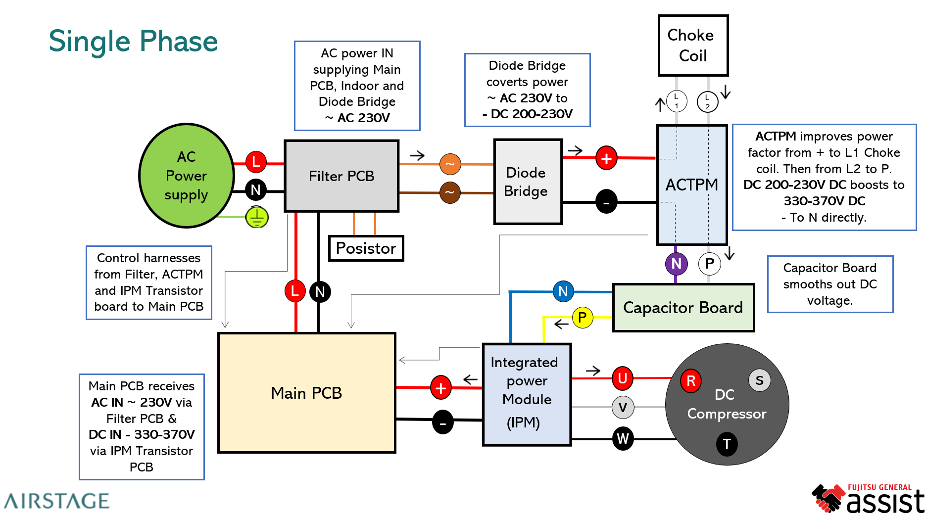
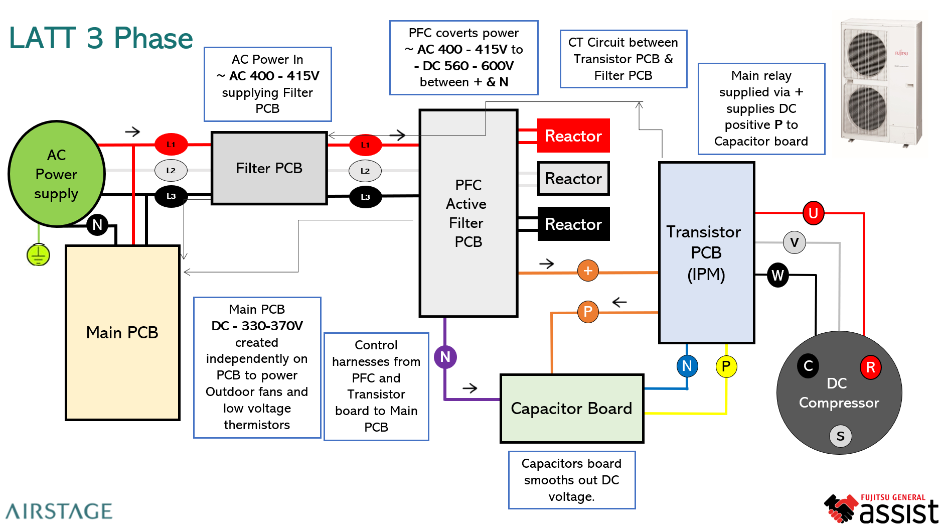
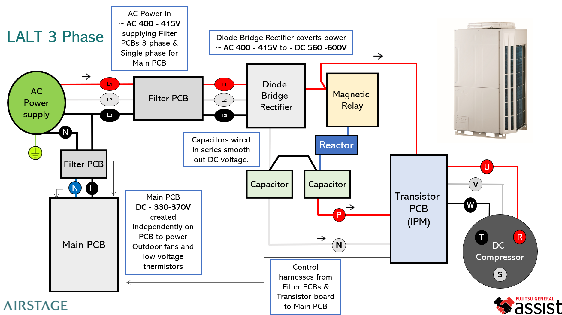
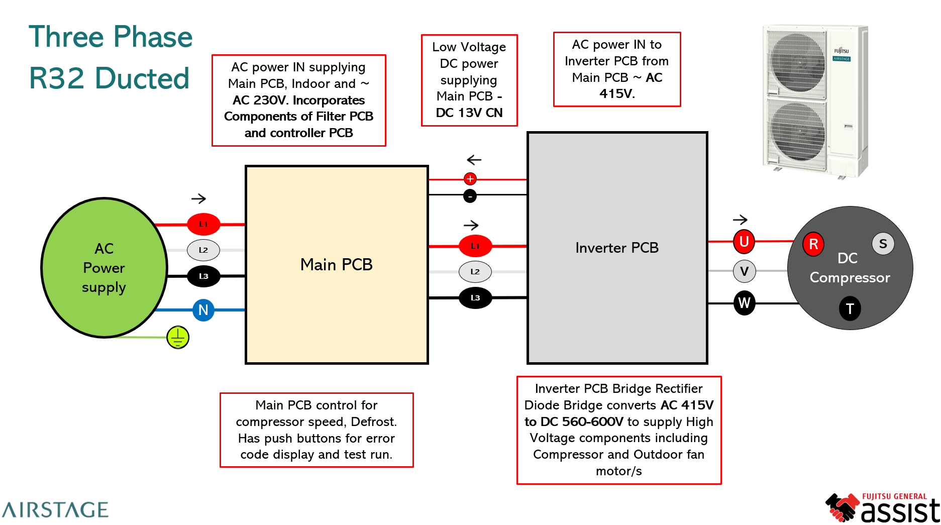
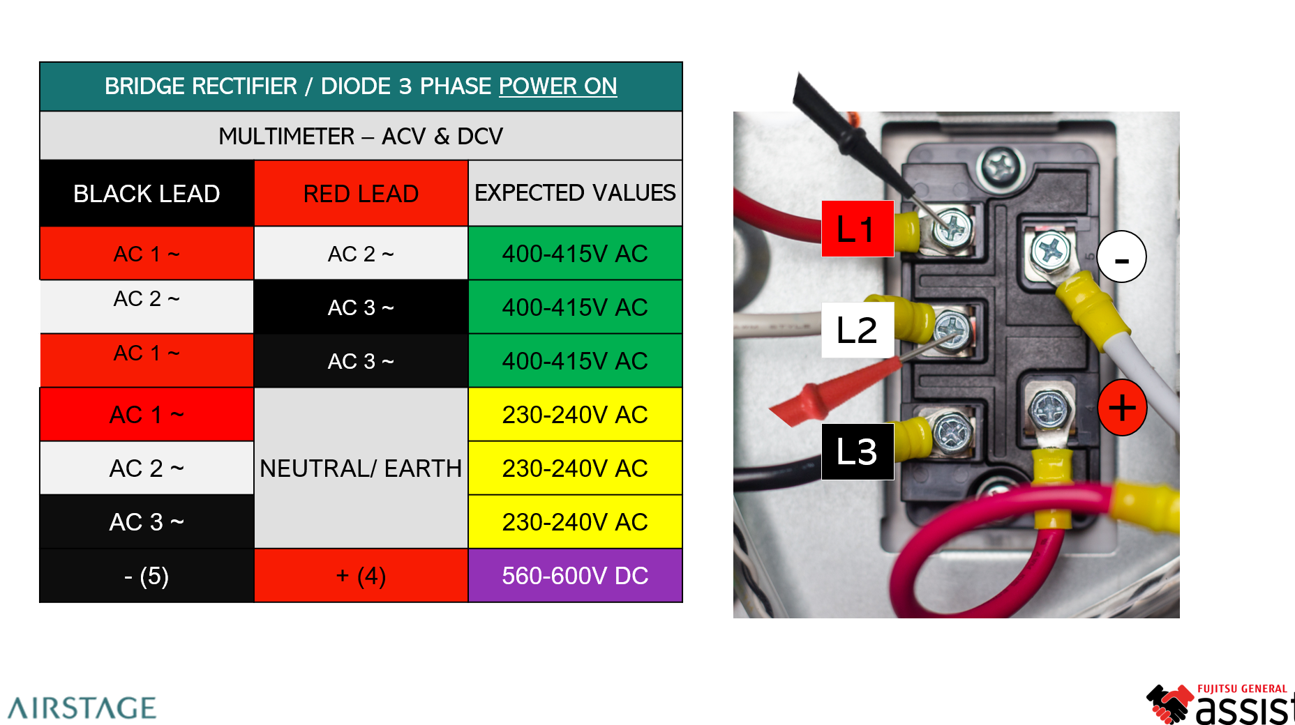
- For a three-phase bridge rectifier, expected phase-to-phase supply is approximately 400-415 VAC.
- Phase-to-neutral / earth supply is approximately 230-240 VAC.
- The rectified DC bus should be approximately 560-600 VDC.
Diode Bridge / Rectifier - Power-Off Test
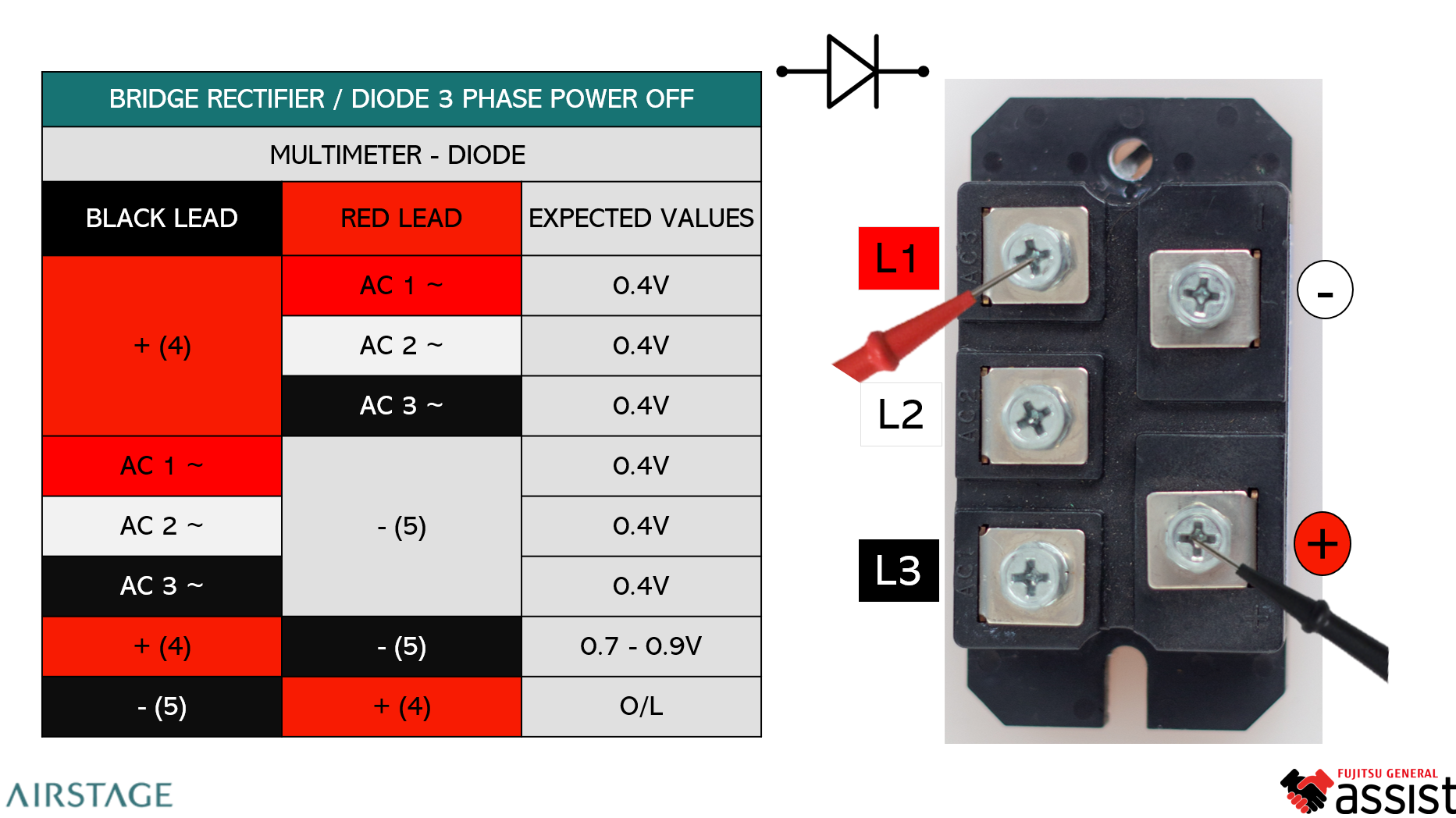
Use the multimeter's Diode Test function when checking the bridge rectifier with the power isolated.
- Isolate electrical power to the unit.
- Allow the DC bus capacitors to discharge and verify that dangerous voltage is no longer present.
- Disconnect the applicable control harnesses / connections so the rectifier is not being measured through the rest of the circuit.
- Set the multimeter to Diode Test.
- Measure the rectifier terminals in both probe directions.
- Compare the readings with the expected values below.
Typical Diode-Test Readings
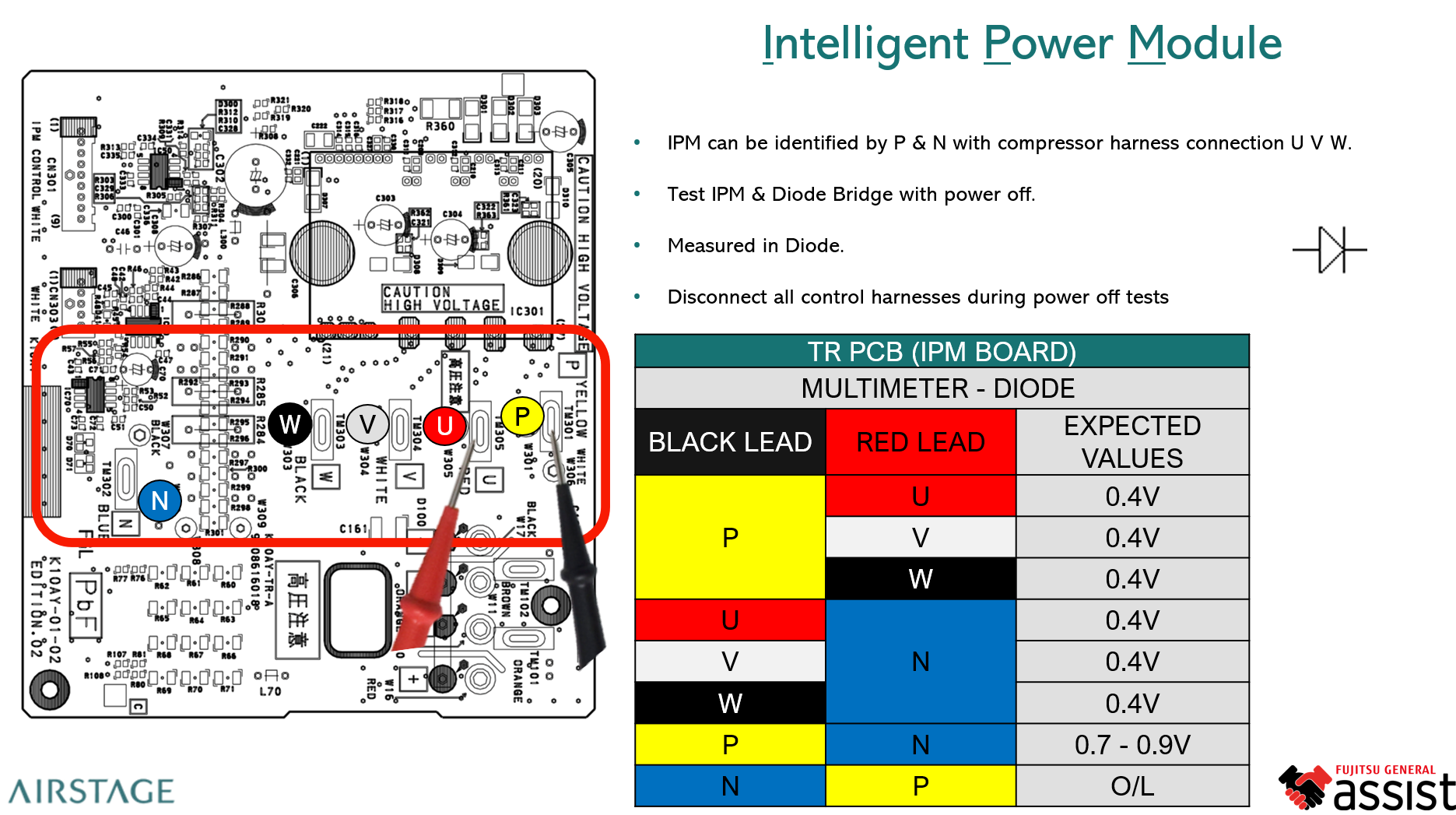
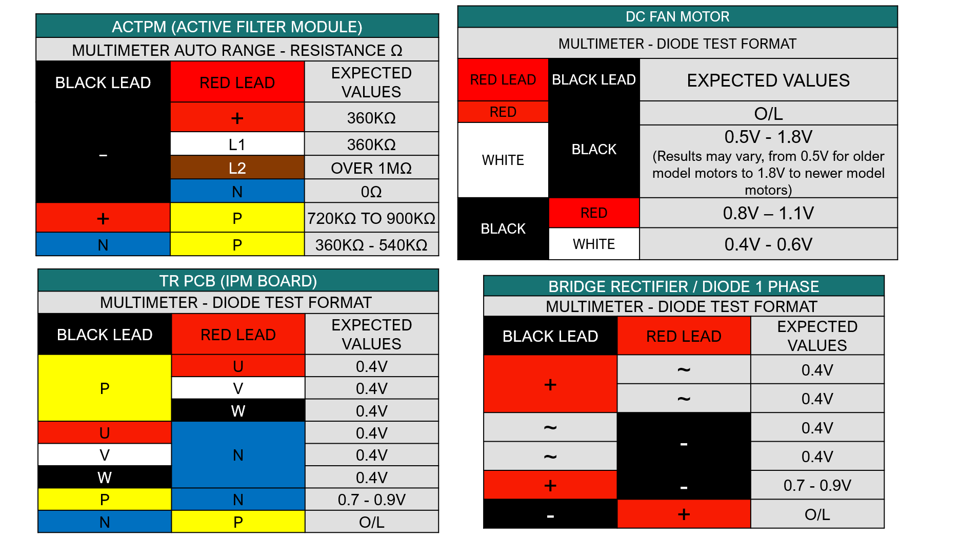
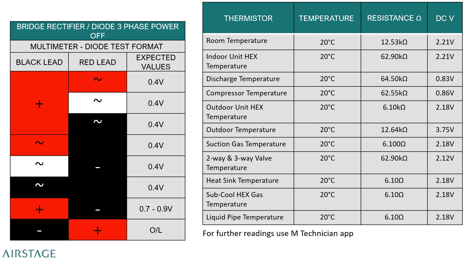
The source training material shows typical forward diode readings of approximately 0.4 V through the individual rectifier paths.
| Test Condition | Typical Expected Reading |
|---|---|
| Forward-biased individual diode path | Approximately 0.4 V |
| One combined diode path shown in the training reference | Approximately 0.7-0.9 V |
| Reverse-biased / non-conducting path | O.L. |
A reading that is effectively short circuit in both directions, or a path that remains open in both directions where conduction is expected, indicates a suspect bridge rectifier.
Three-Phase Bridge Rectifier - Live Voltage Checks
The source shows the following expected supply and DC-bus values for a three-phase bridge rectifier with the system powered.
| Measurement | Expected Value |
|---|---|
| AC1 to AC2 | 400-415 VAC |
| AC2 to AC3 | 400-415 VAC |
| AC1 to AC3 | 400-415 VAC |
| Phase to Neutral / Earth | 230-240 VAC |
| DC Positive (+) to DC Negative (-) | 560-600 VDC |
Correct AC input but missing or abnormal DC output indicates that the bridge rectifier or associated DC-bus circuit requires further investigation.
Three-Phase Bridge Rectifier - Power-Off Diode Checks
With the unit isolated, the source reference shows individual rectifier paths producing approximately 0.4 V in the conducting direction. Other paths may show approximately 0.7-0.9 V or O.L., depending on probe orientation and the internal diode path being tested.
For reliable diagnosis, compare all equivalent phase paths. Similar diode junctions should give reasonably consistent readings.
DC Brushless Fan Motors
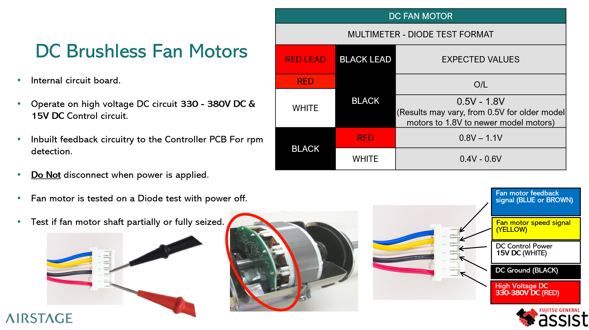
DC brushless fan motors contain an internal electronic circuit board. They are not tested in the same way as a conventional AC fan motor.
- The motor operates from a high-voltage DC supply.
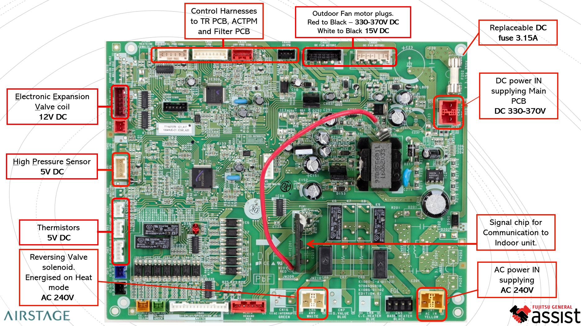
- A separate low-voltage control / feedback circuit is used between the fan motor and controller PCB.
- The fan contains feedback circuitry so the controller PCB can detect motor operation.
- Do not disconnect the fan motor while power is applied.
DC Fan Motor - Preliminary Checks
- Isolate power and verify the DC bus has discharged.
- Check that the fan blade and motor shaft rotate freely.
- Do not continue electrical testing if the shaft is partially or fully seized.
- Inspect the motor harness, terminals and connector for heat damage, poor contact or contamination.
- Use the multimeter in Diode Test mode for the power-off motor checks shown in the applicable service information.
Fan Motor Diode-Test Interpretation
The training reference shows that diode-test readings are taken between the fan motor harness conductors with power removed. Depending on the pair and probe direction, a normal result may be:
- O.L.
- Approximately 0.7-1.8 V on some internal electronic paths
- Approximately 0.8-1.1 V on another control path
- Approximately 0.4-0.6 V on a diode path
Technician Checklist
- Confirm the correct component and wiring diagram.
- Isolate power before diode testing.
- Verify capacitor discharge before touching inverter circuitry.
- Use Diode Test mode, not resistance mode, where specified.
- Compare equivalent diode paths for consistency.
- For live rectifier tests, confirm all three phase-to-phase voltages are present.
- Confirm the DC bus output is within the expected range.
- For DC fan motors, check the shaft mechanically before electrical diagnosis.
- Never unplug a DC brushless fan motor while the system is energised.