
AIRSTAGE Technical Reference
UTY-CDRXZC and UTY-ANY1/2 Zone Motor Wiring
RJ12 pinouts, rewiring requirements and operational verification
For standard 24 V AC zone motors used with Fujitsu ducted zoning and anywAiR or smart zoning interfaces
Both the UTY-CDRXZC and UTY-ANY1/2 controllers can operate standard 24 V AC zone motors. However, their RJ12 pin configurations are different. The RJ12 connector must be rewired to match the controller being used.
Important: Incorrect wiring may cause the damper motor to operate in reverse or fail to respond. Isolate power before altering the RJ12 connector and confirm the pinout before energising the controller.
1. Quick wiring comparison
| Signal | UTY-CDRXZC pins | UTY-ANY pin |
|---|---|---|
| OPEN active | 1 and 2 | 4 |
| COMMON / neutral | 3 and 4 | 3 |
| CLOSE active | 5 and 6 | 2 |
| Not used | None | 1, 5 and 6 |
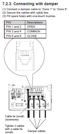
2. UTY-CDRXZC RJ12 pinout
Used with Fujitsu ducted zoning systems, Zones 1–8.
| Pin | Function |
|---|---|
| 1 and 2 | OPEN active |
| 3 and 4 | COMMON / neutral |
| 5 and 6 | CLOSE active |
RJ12 reference layout — UTY-CDRXZC
| 1 | OPEN active |
| 2 | OPEN active |
| 3 | COMMON |
| 4 | COMMON |
| 5 | CLOSE active |
| 6 | CLOSE active |
Wiring notes
- Connect each damper cable from Zone 1 to Zone 8 to its respective port.
- Use cable ties to secure the damper cables.
- Fill unused port holes with one-touch bushes for protection.
- Each damper output provides a 24 V AC switching signal for OPEN, COMMON and CLOSE.
3. UTY-ANY RJ12 pinout
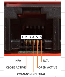
Used with anywAiR or smart zoning interfaces.
| Pin | Function |
|---|---|
| 1 | Not used |
| 2 | CLOSE active |
| 3 | COMMON neutral |
| 4 | OPEN active |
| 5 | Not used |
| 6 | Not used |
RJ12 reference layout — UTY-ANY
| 1 | Not used |
| 2 | CLOSE active |
| 3 | COMMON neutral |
| 4 | OPEN active |
| 5 | Not used |
| 6 | Not used |
4. Rewiring the RJ12 connector
The same 24 V zone motor can be used with either controller, provided the RJ12 connector is re-pinned to match the required wiring scheme.
| Signal | Connect to UTY-CDRXZC | Connect to UTY-ANY |
|---|---|---|
| OPEN | Pin 1 or 2 | Pin 4 |
| COMMON / neutral | Pin 3 or 4 | Pin 3 |
| CLOSE | Pin 5 or 6 | Pin 2 |
Before reconnecting: Confirm that the OPEN, CLOSE and COMMON/neutral conductors are mapped to the correct RJ12 pins. Do not connect an external 24 V transformer; the controller board supplies the motor power.
5. Verification test
- Power on the controller.
- Command the damper to OPEN. The motor or actuator should move to the open position.
- Command the damper to CLOSE. The motor should drive to the closed position.
- If the direction is reversed, isolate power and swap the OPEN and CLOSE conductors.
6. Technical notes
- Both controllers output 24 V AC switching control, not DC.
- Do not connect an external 24 V transformer; power is supplied by the controller board.
- Always confirm the RJ12 pinout before operation.
- Use shielded control cables in multi-zone applications to minimise interference.
Technical information should be confirmed against the applicable product documentation and the wiring labels on the installed equipment.