AIRSTAGE Technical Reference
Electronic Control Components
Functions, operating voltages and inverter-system power flow
Reference guide for key indoor and outdoor-unit electronic components
This article explains the role of the main electronic control components used in Fujitsu General inverter systems. Together, these components convert, regulate and control AC and DC voltages while managing compressor speed, refrigerant flow and sensor feedback.
High-voltage hazard: Inverter equipment can retain dangerous DC voltage after power is isolated. Confirm capacitor discharge with a suitable meter before handling or testing internal components. Work must only be completed by appropriately qualified personnel.
Inverter power and control flow
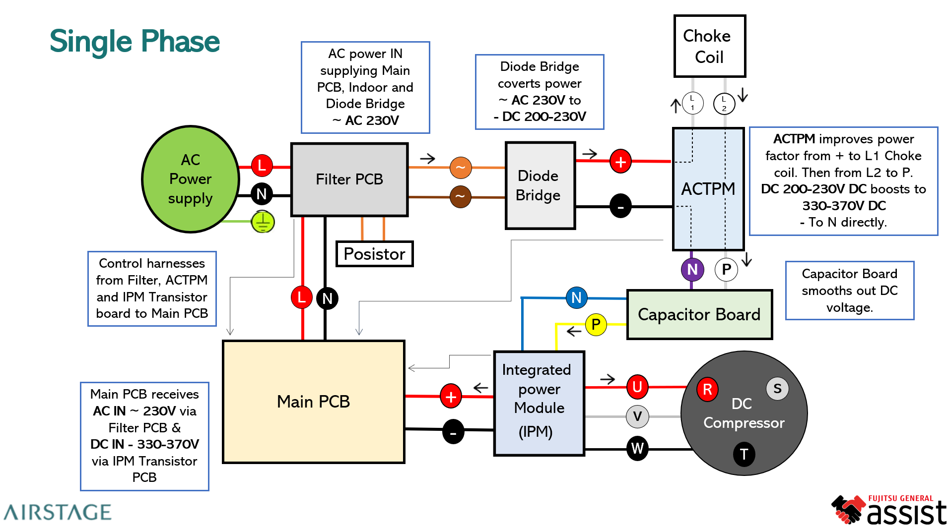
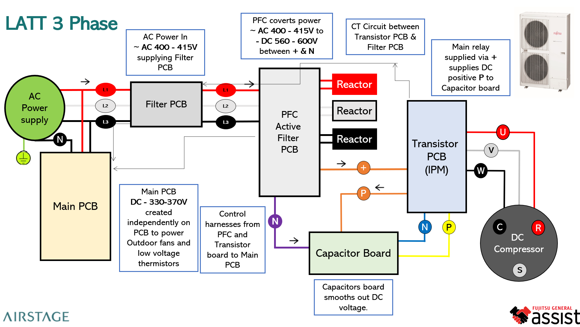
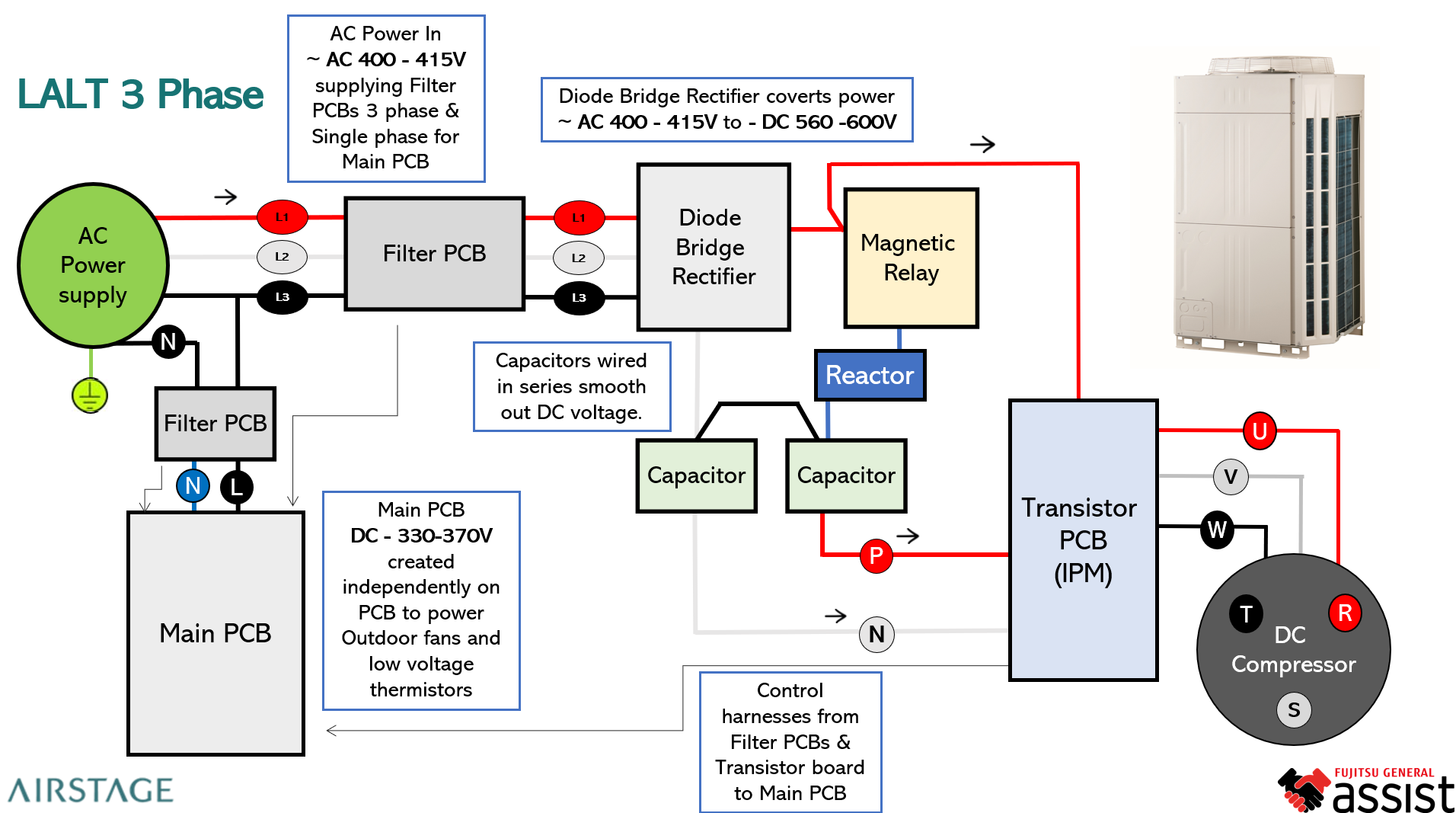
AC Supply → Diode Bridge → ACTPM / PFC → Capacitor Board → IPM → DC Compressor
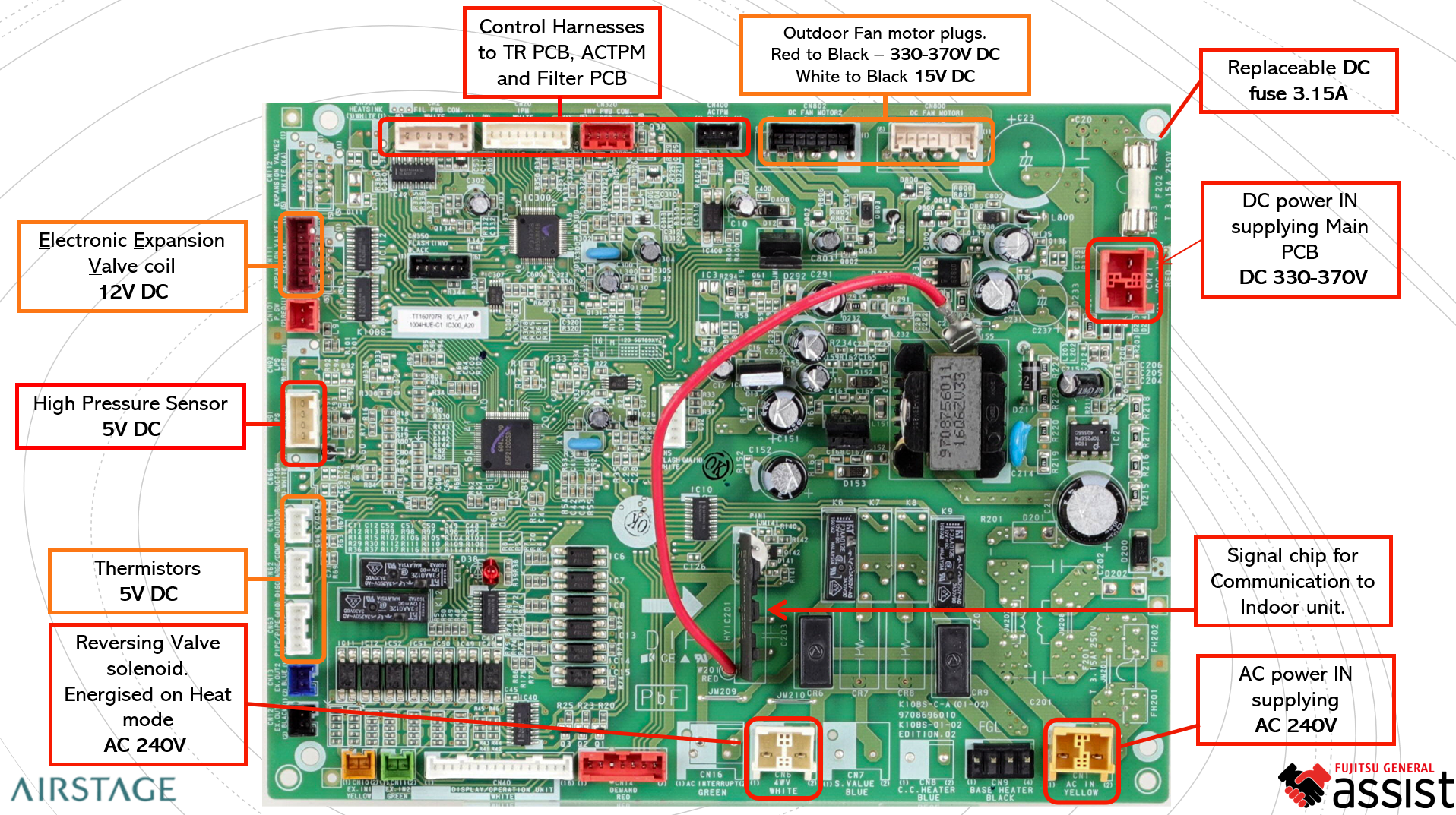
The Main PCB supervises the complete process. It receives temperature, pressure and communication inputs, then regulates the compressor, fans and electronic expansion valve according to operating demand.
Component functions
1. Diode Bridge (Rectifier)
Function: Converts incoming AC voltage into DC voltage as the first stage of DC power generation.
- Supplies rectified DC to the ACTPM or PFC module.
- Verify using the multimeter diode-test function.
- Typical output: 200-230 V DC for single-phase systems and 560-600 V DC for three-phase systems.
2. Active Filter Module (ACTPM / PFC)
Function: Improves power factor, reduces harmonic distortion and boosts the rectified DC voltage.
- Receives rectified DC power from the diode bridge.
- Boosts single-phase DC from approximately 200-230 V to 330-370 V DC.
- Three-phase output is typically 560-600 V DC.
- Common failure symptoms include breaker tripping, low DC output and ACTPM overcurrent errors.
3. Capacitor Board
Function: Smooths the pulsating DC voltage and provides a stable DC bus for the inverter module.
- Contains high-voltage capacitors rated up to 450 V DC.
- Stores and releases energy during inverter modulation.
- Expected output is generally 330-370 V DC for single-phase systems and 560-600 V DC for three-phase systems.
- Always verify safe discharge before handling.
4. Integrated Power Module (IPM) / Transistor Board
Function: Switches the stable DC bus into controlled pulse-width-modulated outputs for the compressor motor.
- Outputs to compressor windings U, V and W.
- Receives frequency and voltage commands from the Main PCB.
- Supports variable-speed compressor control.
- Faults may trigger DC overcurrent, compressor lock or inverter communication errors.
5. Electronic Expansion Valve (EEV)
Function: Precisely meters refrigerant flow into the evaporator according to operating load.
- Operates from 12 V DC pulse signals supplied by the Main PCB.
- Opens and closes in small controlled steps.
- Coil resistance varies by valve type and must be checked against the applicable service data.
6. Pressure Transducer Sensor
Function: Converts refrigerant pressure into a DC voltage signal used by the control system.
- Supply: 5 V DC.
- Output: Typically 0.5-4.5 V DC, proportional to pressure.
- Used for suction, discharge and subcool-pressure monitoring.
- Supports load control and system protection.
7. Main PCB (Control Board)
Function: Coordinates the power stages, sensors, communications and operating outputs.
- Processes temperature, pressure and communication signals.
- Controls compressor frequency, EEV position and fan modulation.
- Common supply levels include 5 V DC for sensors and 12/15 V DC for valves and fans.
- Communicates with the indoor unit through the system communication terminal.
8. DC Compressor
Function: Converts electrical energy into refrigerant compression, with speed controlled by inverter frequency.
- Receives modulated outputs from the IPM at U, V and W.
- Typical winding resistance is 0.3-2.0 ohms, subject to model-specific data.
- Insulation resistance to earth should be greater than 1 megohm.
Key component interconnection summary
| Component | Input | Output / Signal | Primary Role |
|---|---|---|---|
| Diode Bridge | 230-415 V AC | Rectified DC | Converts AC to DC |
| ACTPM / PFC | 200-230 V DC | 330-370 V DC single phase; 560-600 V DC three phase | Boosts DC and improves power factor |
| Capacitor Board | DC bus input | Stabilised DC output | Smooths DC ripple |
| IPM Module | High-voltage DC bus | PWM output to U, V, W | Drives compressor windings |
| EEV | 12 V DC pulses | Step control | Regulates refrigerant flow |
| Pressure Sensor | 5 V DC | 0.5-4.5 V DC feedback | Monitors refrigerant pressure |
| Main PCB | AC / DC supplies and sensor inputs | Logic and power distribution | Central control management |
| DC Compressor | PWM output from IPM | Mechanical compression | Circulates refrigerant |
Important: Voltage and resistance values are typical reference values only. Always confirm the correct limits in the applicable model service manual before replacing a component.
Reference images