
General Assist Technical Reference
VRF Emergency Function
Emergency stop operation, external input and system response
For Fujitsu General / AIRSTAGE VRF applications
The Emergency Function in Fujitsu General VRF systems is designed to provide a coordinated system response during critical situations such as fire emergencies, power failures or other unexpected events. Depending on the system configuration, an emergency input can halt operation or initiate a predefined response to support site safety requirements.
Important: Emergency-stop wiring and configuration should only be completed by suitably qualified personnel. Confirm the applicable outdoor unit, controller and external input requirements before installation or commissioning.
1. Key features
| Feature | Description |
|---|---|
| Immediate system shutdown | Halts system operation during an emergency to reduce potential risks such as fire spread or electrical hazards. |
| Centralised control | Can operate in conjunction with centralised control equipment to provide a coordinated response across connected units. |
| External system integration | Can be triggered by external devices such as fire alarm contacts, manual emergency switches or compatible centralised control equipment. |
| Flexible reset arrangement | The system can be configured for the required reset behaviour after the emergency condition has been cleared. |
2. Typical use cases
- Commercial buildings: Provides an immediate HVAC response when a fire alarm or other site safety input is activated.
- Industrial facilities: Supports coordinated shutdown across larger multi-zone installations.
- Hotels and hospitals: Allows HVAC operation to be stopped as part of the site's emergency response strategy.
3. Setting up the Emergency Function
Before starting: Confirm the exact VRF outdoor unit model, applicable external connection kit, PCB connector locations and function-setting requirements from the relevant installation or technical documentation.
- Install the external connection kit
- Ensure the required optional external connection kit is installed. An example referenced for this application is UTY-XWZXZ7.
- Connect the external emergency device
- Connect the fire alarm contact or manual emergency switch to the specified outdoor unit PCB input terminals.
- Connector references may include CN6 and CN7, depending on the applicable model and control arrangement.
- Follow the specified wiring requirements. The source information references wiring in the AWG 22-20 range.
- Configure the Emergency Function
- Access the applicable function-setting menu using the supported remote controller or centralised control interface.
- The source information identifies Function No. 50 for Emergency Stop.
- Select the required setting for the desired reset behaviour.
| Item | Referenced information |
|---|---|
| External connection kit | UTY-XWZXZ7 example |
| Outdoor PCB connectors | CN6 / CN7 examples |
| Wiring | AWG 22-20 referenced |
| Function number | 50 - Emergency Stop |
4. Testing the configuration
- Confirm all emergency input wiring and function settings are complete.
- Place the VRF system in normal operation.
- Simulate the external emergency trigger, such as activation of the connected fire alarm contact or emergency switch.
- Verify the VRF system responds in accordance with the configured emergency-stop operation.
- Clear the emergency input and confirm the system follows the configured reset behaviour.
Commissioning requirement: Do not rely on configuration alone. The complete emergency input sequence should be functionally tested as part of commissioning and coordinated with the site's fire or building-management requirements.
5. Reference image
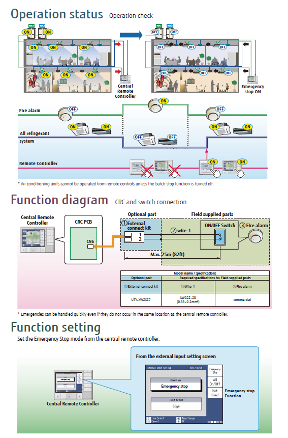
Always confirm model-specific wiring, connector locations and function settings against the applicable Fujitsu General / AIRSTAGE technical documentation before installation or commissioning.