AIRSTAGE VRF Technical Reference
Keycard Interlock Function
Energy-saving room control for hotels, accommodation and intermittently occupied spaces
Overview, typical applications, external connection requirements and function setup
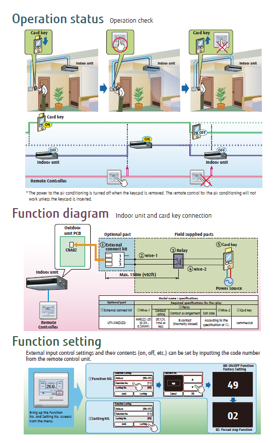
The Keycard Interlock Function in Fujitsu General VRF systems provides an energy-management solution commonly used in hotels and guest accommodation. Air conditioning and associated lighting can be enabled when a keycard is inserted and switched off when the keycard is removed, helping reduce unnecessary operation while a room is unoccupied.
1. Key features
| Feature | Description |
|---|---|
| Automatic On/Off operation | Activates air conditioning and lighting when a keycard is inserted and automatically turns the systems off when the keycard is removed. |
| Energy efficiency | Helps prevent unnecessary energy use by limiting operation to periods when the room is occupied. |
| External device integration | Designed to operate with an external keycard system for coordinated room control. |
| Customisable settings | Operational parameters can be configured, including settings associated with system response when the keycard is removed. |
2. Typical use cases
Hotels and guest rooms
Helps ensure air conditioning and lighting are switched off when guests leave the room and remove the keycard.
Helps ensure air conditioning and lighting are switched off when guests leave the room and remove the keycard.
Conference rooms
Allows room operation to be linked to occupancy for improved energy management.
Allows room operation to be linked to occupancy for improved energy management.
Office spaces
Provides an energy-efficient control option for spaces that are occupied intermittently.
Provides an energy-efficient control option for spaces that are occupied intermittently.
3. Setting up the Keycard Interlock Function
| Step | Action | Details |
|---|---|---|
| 1 | Install the external connection kit | Connect the keycard system to the VRF indoor unit using the applicable external connection kit, for example UTY-XWZXZD. |
| 2 | Connect the keycard reader | Wire the keycard reader to the indoor unit terminals in accordance with the applicable wiring specifications. |
| 3 | Configure the function parameters | Access the VRF function setup using the applicable remote controller or control interface, then configure the required Function No. and Setting No. |
| 4 | Test the configuration | Insert and remove the keycard and confirm that the connected system responds as intended. |
Function setting
Function No.: 49
Setting No.: Configure the applicable operational response or delay setting for the installation.
Function No.: 49
Setting No.: Configure the applicable operational response or delay setting for the installation.
Installation note: Confirm the applicable indoor-unit external input specifications and connection kit before wiring. Connection requirements can vary by indoor unit and system configuration.
4. Reference image