AIRSTAGE Technical Reference
Peak Cut Power Consumption Function
VRF energy demand management and power consumption limitation
For Fujitsu General VRF systems using the Peak Cut function
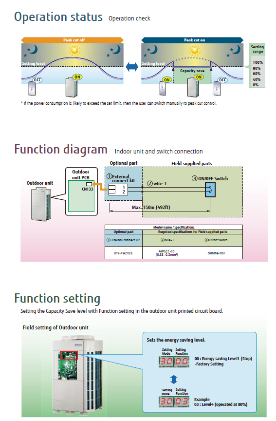
The Peak Cut Power Consumption Function is designed to optimise energy use during periods of high demand. It limits VRF system power consumption to a preset threshold, helping manage peak electrical demand and reduce the risk of peak demand charges.
1. Key features
| Feature | Description |
|---|---|
| Power consumption limitation | Allows the VRF system's power consumption to be capped at selected levels from 40% to 100% of maximum capacity. |
| Customisable settings | Selectable power-saving levels can be matched to the operational needs of the facility. |
| Manual or automatic activation | The function can be triggered manually or integrated with an external system for automated control. |
| Peak-hour energy management | Limits system power during peak periods to help manage electricity demand charges. |
2. Typical use cases
Mega shopping malls
Reduce power consumption during peak shopping hours while maintaining building comfort.
Reduce power consumption during peak shopping hours while maintaining building comfort.
Factories
Manage HVAC energy use during high-demand production schedules.
Manage HVAC energy use during high-demand production schedules.
Glass-panelled buildings
Control cooling loads in areas subject to high temperature fluctuations.
Control cooling loads in areas subject to high temperature fluctuations.
3. Setting up the Peak Cut function
- Install the necessary hardware.
Ensure the outdoor unit PCB is equipped with the external connection kit, for example UTY-XWZXZ6. - Access the function settings.
Use the remote controller or centralised control panel to navigate to the function setup menu. - Set the peak power limit.
Locate Function No. 03 and configure the required power-saving level. - Activate the function.
Enable the Peak Cut function from the settings menu. Where required, link it to an external control system for automated peak-hour activation.
4. Peak Cut power levels
| Function No. | Power limit | Notes |
|---|---|---|
| 03 | 40% | Maximum power-saving level listed. |
| 60% | Intermediate power limit. | |
| 80% | Reduced peak consumption with greater available capacity. | |
| 100% | Default. Full available capacity. |
Comfort consideration: Lower Peak Cut settings reduce the power available to the system. If heating or cooling performance is insufficient, review the selected capacity limit against the building load requirements.
5. Troubleshooting
| Issue | Checks / actions |
|---|---|
| Peak Cut function not activating |
|
| Insufficient cooling or heating |
|
| System exceeds the intended power limit |
|
6. Reference image