
General Assist Technical Reference
Anywair (1) Remote Sensor Configuration Guide
Return air and Mainzone temperature-sensor selection
For Anywair ducted control systems using the red control module and wireless zone sensors
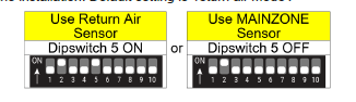
The Anywair ducted controller can regulate the system using either the return air sensor or the Mainzone wall sensor. The sensor source is selected through DIP switch 5 inside the red Anywair control module.
Important: Isolate power before opening the control module or changing DIP-switch settings. Settings should only be adjusted by suitably qualified personnel.
1. Mainzone and return air sensor selection
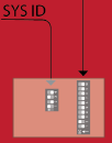
Location: DIP switch bank inside the red Anywair control module, normally installed in the roof cavity.
| Temperature reference | DIP switch | Setting | Operation |
|---|---|---|---|
| Return air sensor | 5 | ON | The system uses the return air sensor as the temperature reference. This is the factory-default setting. |
| Mainzone sensor | 5 | OFF | The system uses the Mainzone wall sensor as the primary temperature-control point. |
2. Configuration procedure
- Isolate power to the air-conditioning and Anywair control system.
- Locate the red Anywair control module in the roof cavity.
- Open the module and identify the DIP-switch bank marked SYS ID.
- Set DIP switch 5to the required position:
- ON: use the return air sensor.
- OFF: use the Mainzone wall sensor.
- Close the module securely and restore power.
- Allow the controller to restart, then confirm the selected sensor is reporting a reasonable room temperature.
3. Wireless remote sensor addressing
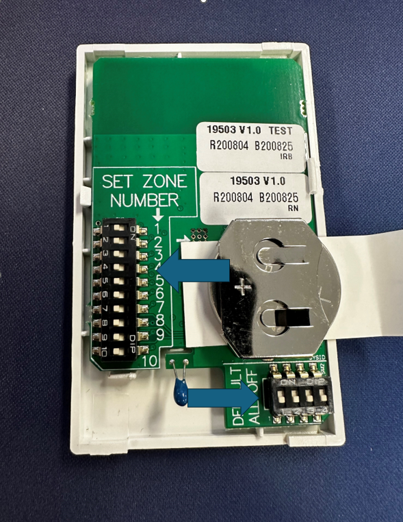
Each wireless sensor must be assigned to the correct zone so the controller can associate its temperature reading with that zone. The sensor contains a numbered DIP-switch bank labelled SET ZONE NUMBER.
Set each sensor to the zone number it serves and ensure no two sensors are assigned to the same zone unless the system design specifically requires it. Do not change the smaller auxiliary DIP-switch bank unless directed by the applicable installation instructions.
4. Final checks
- Confirm DIP switch 5 is fully seated in the selected ON or OFF position.
- Confirm the Mainzone sensor is installed and communicating before selecting it as the control reference.
- Confirm each wireless sensor is assigned to the intended zone number.
- Check that the displayed temperature is realistic and responds to changes around the selected sensor.
- Confirm normal heating and cooling operation after restoring power.
Configuration summary: DIP switch 5 ON selects the return air sensor. DIP switch 5 OFF selects the Mainzone wall sensor.
Technical information should be verified against the applicable installation documentation and the actual equipment configuration before changes are made.