
General Assist Technical Reference
8-Port and 12-Port Refrigerant Branch Box Addressing
S300 concurrent-output settings for merged RB Unit branches
Applicable to General AIRSTAGE VRF installations using 8-port or 12-port Refrigerant Branch Boxes
When two or more outlets from an 8-port or 12-port Refrigerant Branch Box are combined to serve one indoor refrigerant circuit, the applicable S300 concurrent-output DIP switches must be configured to match the physical piping arrangement.
Important: Incorrect S300 settings or connection to the wrong branch terminal may cause communication errors, incorrect electronic expansion valve operation, an indoor unit shortage indication or an RB Unit fault.
1. Configuration principle
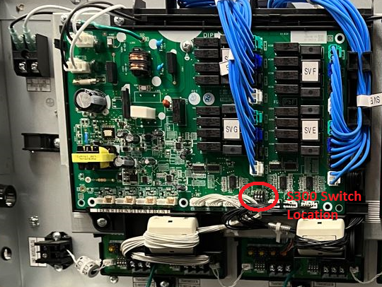
Each RB control PCB manages a group of four sequential branch outputs. The S300 DIP switch determines which outlets within that four-port group operate concurrently as one combined refrigerant branch.
| RB Unit | PCB branch groups | Available merged groups |
|---|---|---|
| 8-port RB Unit | A-D and E-H | Two sequential ports or all four ports within either group |
| 12-port RB Unit | A-D, E-H and I-L | Two sequential ports or all four ports within any group |
Connection rule: When outlets are merged, connect the indoor-unit communication cable and the combined branch circuit to the last or lower-lettered terminal shown in the applicable group: B, D, F, H, J or L.
2. Merging two ports
Use the following S300 settings when combining one sequential pair of outlets.
| PCB branch section | Branches merged | S300-1 | S300-2 | S300-3 | Cable terminal connection |
|---|---|---|---|---|---|
| Branches A-D | A + B | OFF | OFF | ON | Branch B terminal |
| C + D | ON | OFF | OFF | Branch D terminal | |
| Branches E-H | E + F | OFF | ON | OFF | Branch F terminal |
| G + H | OFF | OFF | ON | Branch H terminal | |
| Branches I-L | I + J | ON | OFF | OFF | Branch J terminal |
| K + L | OFF | ON | ON | Branch L terminal |
Two-port merge requirements
- Only merge the sequential pairs shown in the table.
- Do not combine non-sequential outlets such as B + C or D + E.
- Terminate the merged branch on B, D, F, H, J or L as applicable.
3. Merging four ports
When all four outlets managed by one RB PCB are combined, set S300-1, S300-2 and S300-3 to ON.
| PCB branch section | Branches merged | S300-1 | S300-2 | S300-3 | Cable terminal connection |
|---|---|---|---|---|---|
| Branches A-D | A + B + C + D | ON | ON | ON | Branch D terminal |
| Branches E-H | E + F + G + H | ON | ON | ON | Branch H terminal |
| Branches I-L | I + J + K + L | ON | ON | ON | Branch L terminal |
Four-port merge rule: All refrigerant branch connections and the associated indoor-unit communication connection must terminate at the final outlet of the four-port group: D, H or L.
4. Configuration procedure
1
Confirm the design. Verify which sequential outlets are physically combined and confirm that the merged arrangement is permitted for the applicable RB Unit.
2
Isolate all power. Turn off the outdoor unit and RB Unit power before opening the enclosure or changing DIP switches.
3
Locate S300. Identify the S300 concurrent-output DIP switch on the PCB that controls the applicable four-port branch group.
4
Set the switches. Apply the S300-1, S300-2 and S300-3 positions shown in the relevant table. Confirm the physical ON direction printed on the PCB.
5
Check the terminal connection. Connect the merged circuit to the designated final branch terminal: B, D, F, H, J or L.
6
Inspect transmission wiring. Confirm the correct transmission terminals, cable continuity and secure connections between the outdoor unit, RB Unit and indoor unit.
7
Restore power and initialise. Complete the model-specific system initialisation or commissioning process so the outdoor unit registers the configured RB branches.
8
Verify operation. Confirm that every indoor unit on the merged branch operates correctly and that no RB Unit or indoor-unit shortage error remains.
Commissioning note: Use the initialisation, address registration and test-run procedure specified for the applicable outdoor unit. Do not use a forced cooling function as a substitute for system initialisation unless the service documentation specifically directs this for the model being commissioned.
5. Installation and wiring notes
- Each PCB controls one four-port branch section. Confirm that changes are made on the PCB associated with the required outlets.
- Always isolate the complete VRF system before changing S300 settings.
- Confirm the transmission wiring is connected to the correct terminals throughout the system. Follow the applicable wiring diagram and installation manual.
- Ensure merged refrigerant piping, connected indoor capacity and piping lengths remain within the manufacturer's design limitations.
- Clearly label the merged outlets and final connection terminal inside the RB enclosure for future servicing.
- Photograph the final S300 positions and branch connections as part of the commissioning record.
6. Common field errors and corrective action
| Symptom | Likely cause | Corrective action |
|---|---|---|
| One indoor unit does not cool or heat on a merged pair | S300 setting does not match the connected pair, or the circuit is connected to the wrong branch terminal. | Recheck the relevant two-port setting and confirm connection to B, D, F, H, J or L. |
| RB Unit error lamp flashes | Incorrect terminal connection, damaged transmission wiring, loose connection or communication fault. | Check the terminal selection, continuity, connections and applicable communication voltage before assessing the PCB. |
| Indoor unit shortage or quantity error | The S300 configuration does not match the piping layout, or the system was not reinitialised after configuration. | Correct the DIP switch arrangement and repeat the model-specific initialisation or address registration process. |
| No operation from the merged group | Incorrect S300 setting, connection to the wrong terminal, wiring fault or control PCB failure. | Confirm configuration and wiring first. Test the relevant PCB only after the external circuit has been verified. |
| Incorrect refrigerant distribution or unstable operation | Merged outlets are not sequential, the branch is connected to the wrong output, or the piping design is outside permitted limits. | Compare the physical installation with the approved piping design and correct the branch grouping or connection point. |
Need further technical assistance?
Contact General Assist and provide the outdoor unit model, RB Unit model, merged branch arrangement, S300 switch positions, terminal connection used and any active error codes.