
General Assist Technical Reference
Refrigerant Branch Box (RB Unit) Error Indication
LED status interpretation and field diagnostic guidance
For GENERAL AIRSTAGE VRF refrigerant branch units
The Refrigerant Branch Box, also referred to as the RB Unit, distributes refrigerant between the outdoor unit and connected indoor units. The onboard green and red indicator lamps provide immediate diagnostic information to assist with identifying normal operation, incorrect transmission wiring and communication or PCB faults.
Safety requirement: Isolate power to the complete VRF system before changing transmission wiring, checking terminals or replacing a PCB. Failure to isolate power may damage the control boards or expose personnel to electrical hazards.
1. Indicator lamp reference
| Indicator lamp | Description |
|---|---|
| Power Indicator Lamp - Green | Confirms that power is supplied and indicates the RB Unit's communication readiness. |
| Error Indicator Lamp - Red | Indicates incorrect wiring, a communication failure or an internal PCB fault, depending on the lamp pattern. |
2. Status display and fault interpretation
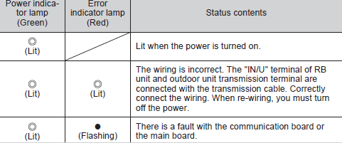
| Green power lamp | Red error lamp | Status or likely cause | Recommended action |
|---|---|---|---|
| Steady ON | OFF | Normal operation. Power is supplied and no RB Unit error is present. | No action is required. |
| Steady ON | Steady ON | Transmission wiring fault. The RB Unit IN/U terminal and outdoor unit transmission terminal may be incorrectly connected, or the transmission cable may be connected to the wrong terminal. | Turn the power OFF before re-wiring. Connect the transmission cable to the correct outdoor unit and RB Unit terminals. Confirm the U1/U2 terminal arrangement against the applicable installation manual. |
| Steady ON | Flashing | Communication fault. Communication between the RB Unit and the outdoor main control PCB has failed. Possible causes include an open circuit, reversed or incorrect wiring, an RB communication PCB fault or an outdoor main PCB fault. | Check cable continuity, terminal connections and transmission voltage. Where the wiring and voltage are correct, isolate the system and test or replace the suspected PCB in accordance with the service manual. |
Transmission voltage guide: A reading of approximately 30-35 V DC may be present on the VRF transmission circuit. Always confirm the expected value and test method in the applicable model's service documentation before condemning a PCB.
3. Applicable RB Unit configurations
The same general LED fault logic applies across the following Refrigerant Branch Box configurations:
| Single-port RB Unit | 4-port RB Unit | 8-port RB Unit | 12-port RB Unit |
Terminal names and board layouts may vary by model. Refer to the installation or service manual for the specific RB Unit before testing or changing wiring.
4. Field diagnostic procedure
1
Record the LED condition. Confirm whether each lamp is OFF, steadily illuminated or flashing before cycling power.
2
Isolate the system. Turn off the outdoor unit and associated control power before touching terminals or disconnecting a PCB.
3
Inspect the transmission wiring. Check the correct terminals, cable continuity, loose connections, shorts to earth and any signs of damage or crossed wiring.
4
Restore power and test. Re-energise the system only after all wiring has been secured. Allow the control network sufficient time to initialise before reassessing the LEDs.
5
Check the PCB and supply. Where the LEDs remain abnormal, confirm the relevant control supply and transmission voltage before replacing the RB Unit communication PCB or outdoor main PCB.
5. Additional diagnostic notes
- If neither indicator lamp illuminates, check the RB Unit power supply, wiring and applicable fuse or protection device.
- After correcting wiring or replacing a PCB, complete the required system reset or power-cycle procedure.
- Do not replace a PCB solely from an LED indication. Confirm wiring integrity, terminal selection and voltage first.
- Persistent flashing with confirmed-good wiring may indicate an RB Unit communication PCB or outdoor main control PCB failure.
- Record the RB Unit model, serial number, LED pattern and measured voltages when escalating the case to Technical Support.
Need further technical assistance?
Contact General Assist and provide the outdoor unit model, RB Unit model, LED status, wiring checks completed and any measured transmission voltages.