
General Assist Technical Procedure
R32 Ducted Inverter PCB Access
Safe access to the outdoor main PCB, electrical module and inverter PCB assembly
For applicable General / AIRSTAGE R32 ducted outdoor units
This procedure outlines the sequence for accessing the inverter PCB without removing the outdoor unit top or side panels. Correct isolation, DC-voltage verification and careful handling of connectors are essential to prevent electric shock, equipment damage and repeat failures.
High-voltage warning: The inverter circuit can retain hazardous DC voltage after mains power has been isolated. This work must only be completed by suitably qualified refrigeration or electrical service personnel using an appropriately rated multimeter and approved isolation procedures.
1. Preparation and service-panel access
| 1 | Stop the air conditioner using the controller and allow the system to complete its normal shutdown sequence. |
| 2 | Identify and remove the service-panel retaining screws. |
| 3 | Remove the service panel to expose the electrical module. The top and side panels do not normally need to be removed for this procedure.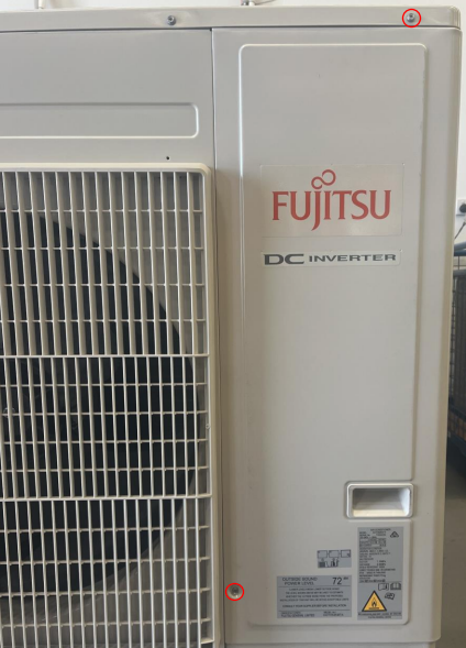 |
Before disconnecting anything: Photograph the PCB, plugs, harness routing, terminal connections and earth leads. Label similar connectors where required to prevent incorrect reconnection.
2. Isolate power and verify safe voltage
Do not rely solely on the main PCB LEDs being off. The DC bus must be measured and confirmed at a safe level before touching or disconnecting inverter components.
| Check | Required action |
|---|---|
| AC supply | Isolate and lock out the outdoor unit supply. Confirm no voltage at L–N, L–Earth and N–Earth using an approved meter. |
| Main PCB status | Confirm all main PCB display LEDs are off after the specified discharge period. |
| DC high voltage | Measure across the identified DC high-voltage test points or applicable red/black circuit points shown in the model service manual. Proceed only when the measured voltage is within the manufacturer's safe-discharge limit. |
| Meter verification | Prove the meter on a known live source before and after testing.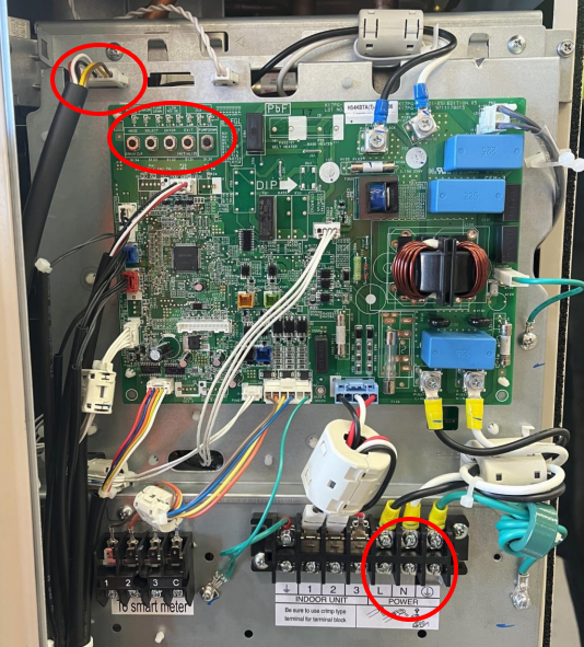 |
3. Remove the outdoor main PCB
- Once both AC and DC voltages have been confirmed safe, disconnect all plugs, screw terminals and earth connections from the outdoor main PCB.
- Release locking tabs before withdrawing plugs. Pull on connector bodies only; do not pull on wires.
- Keep fine-thread screws and terminal hardware separated and identified.
- Release the four PCB corner retaining tabs and lift the main PCB clear of the mounting plate.
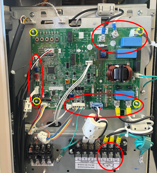
Important: Do not force a connector or lever directly against PCB components. Several plugs and locking tabs are fragile and may be damaged if removed at an angle.
4. Release the electrical mounting plate
| 1 | With the main PCB removed, identify the inverter-module and heatsink retaining screws accessible through the mounting plate. |
| 2 | Remove the fine-thread inverter PCB retaining screw and the seven heatsink screws shown for the applicable assembly. Retain each screw in its correct group.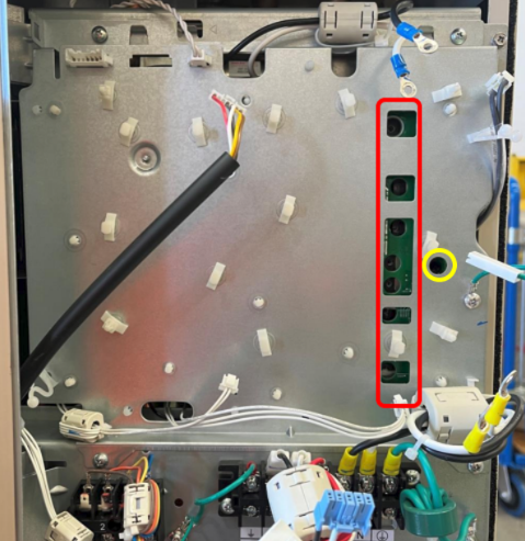 |
| 3 | Disconnect the outdoor fan-motor plug and pressure-switch plug.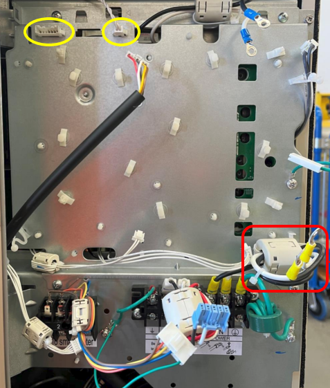 |
| 4 | Disconnect the mains harness and release the EMI-filter harness from the removable cable-tie mount by depressing its retaining tab. |
| 5 | Move all harnesses away from the centre of the electrical module so they cannot snag when the plate is moved. |
| 6 | Remove the four screws securing the mounting plate to the module frame.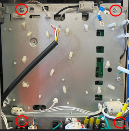 |
5. Access the inverter PCB assembly
- Support the electrical module and pull it forward carefully. Confirm no harnesses, earth leads or refrigerant components are under tension.
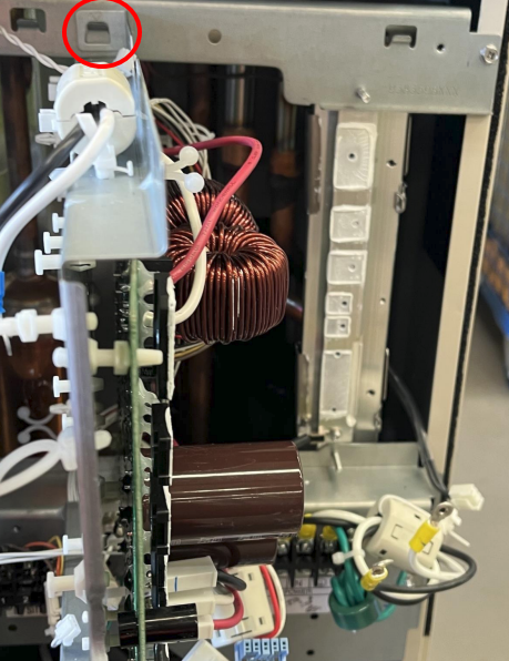
- Align the marked hook point on the module plate with the corresponding hook point on the frame.
- Securely hang the module in the service position before releasing your support.
- The inverter PCB and heatsink assembly can now be accessed from behind the mounting plate.
- Before removal, record all connector positions, PCB revision details, thermal-interface locations and screw arrangements.
Thermal interface: Where an inverter module or heatsink-mounted device is replaced, clean and renew the approved thermal compound or thermal pad exactly as specified in the service manual. Incomplete contact can lead to rapid overheating and repeat failure.
6. Reassembly and testing
| Stage | Requirement |
|---|---|
| Mechanical reassembly | Reinstall all components in reverse order. Use the correct screw type and tighten heatsink fasteners evenly to the manufacturer's specified torque. |
| Harnesses | Confirm every plug is fully seated and locked. Restore original cable routing, clips, cable ties and separation from hot or moving components. |
| Earth connections | Reinstall all earth leads and confirm secure metal-to-metal contact. |
| Pre-power inspection | Check for trapped wires, loose screws, missing insulation barriers, displaced ferrite cores and incorrect terminal placement. |
| Functional test | Restore power, confirm normal PCB LED activity, check for fault codes and complete a system test run in accordance with the service manual. |
7. Service record requirements
- Outdoor-unit model and serial number
- Removed and replacement PCB part numbers and revision codes
- Measured AC and DC voltages before disassembly
- Thermal compound or pad replaced, where applicable
- Test-run results and any fault history
- Clear photographs before and after repair
Completion standard: The electrical module must be securely mounted, all barriers and service panels refitted, no harnesses under strain, and the unit operating without abnormal noise, smell, heat or fault indication.