General Assist Technical Reference
Electronic Expansion Valve (EEV) - Explanation and Testing
Function, operation, 5-wire and 6-wire coil testing
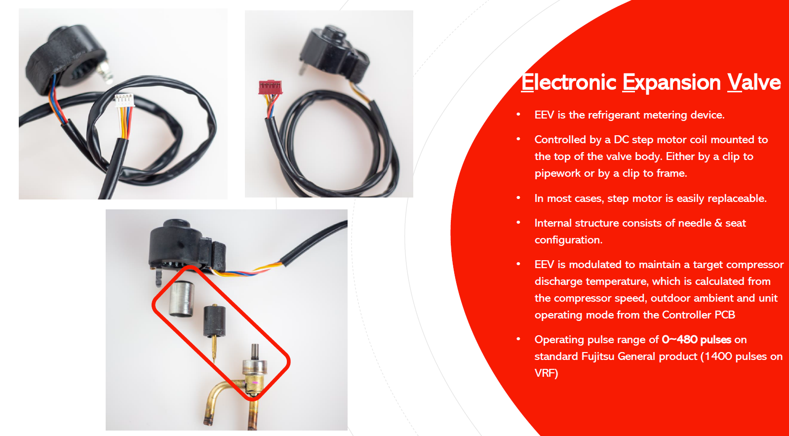
The Electronic Expansion Valve (EEV) is the refrigerant metering device. It is operated by a DC step motor mounted on the valve body and is electronically positioned by the controller PCB to regulate refrigerant flow.
How the Electronic Expansion Valve works
| Item | Explanation |
|---|---|
| Primary function | Meters refrigerant flow through the refrigeration circuit. |
| Drive mechanism | A DC step motor coil is mounted on top of the valve body. Depending on the product, the coil may be clipped to the pipework or clipped to the frame. |
| Internal valve | The valve body uses a needle-and-seat configuration to regulate refrigerant flow. |
| Control | The controller PCB modulates the EEV to maintain a target compressor discharge temperature. |
| Inputs used by control | The target is calculated using compressor speed, outdoor ambient temperature and the unit operating mode. |
| Typical pulse range | 0-480 pulses on standard Fujitsu General products. The supplied training material notes 1400 pulses on VRF. |
| Serviceability | In most cases, the step motor coil is easily replaceable. |
What happens at initial power-up?
During initial power-up, the valve may be heard ticking. This is the step motor driving the EEV fully closed as part of its initialisation.
Normal initialisation: The supplied technical information states that the EEV is driven closed for approximately 500 pulses during initial power-up. A ticking sound from the valve during this period can therefore be normal.
EEV step motor coil testing
Safety: Isolate power before disconnecting or resistance-testing the EEV coil. Follow the applicable service manual and electrical safety procedures for the product being serviced.
5-wire EEV coil
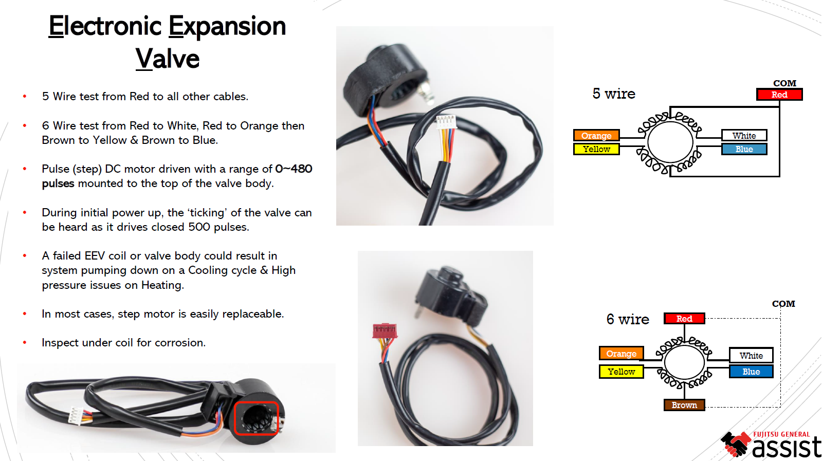
For a 5-wire EEV, use the Red wire as the common reference and test from Red to each of the other four wires.
| Common | Test to |
|---|---|
| Red | White |
| Blue | |
| Orange | |
| Yellow |
6-wire EEV coil
The 6-wire coil uses two common references. Test the coil as follows:
| Common | Test to |
|---|---|
| Red | White |
| Orange | |
| Brown | Yellow |
| Blue |
Resistance values: The supplied reference explains which wire pairs are to be tested but does not specify an acceptable resistance value. Use the relevant model service manual for the required resistance specification and test criteria.
Possible symptoms of an EEV fault
A failed EEV coil or a mechanical fault in the valve body may prevent the valve from positioning correctly. The supplied training material identifies the following possible operating symptoms:
| Operating mode | Possible symptom |
|---|---|
| Cooling | The system may pump down. |
| Heating | High-pressure problems may occur. |
Physical inspection
- Inspect the EEV step motor coil and wiring for damage.
- Remove or lift the coil as appropriate and inspect under the coil for corrosion.
- Confirm the coil is correctly located on the valve body and that its retaining clip or mounting is secure.
- Where the coil is serviceable separately, the step motor can generally be replaced without replacing the complete valve body.
Quick reference
| Check | Reference |
|---|---|
| Standard EEV operating range | 0-480 pulses |
| VRF reference | 1400 pulses |
| Initial power-up | Valve drives closed for approximately 500 pulses; ticking may be audible |
| 5-wire test | Red to White, Blue, Orange and Yellow |
| 6-wire test | Red to White and Orange; Brown to Yellow and Blue |
| Inspection point | Check under the coil for corrosion |
Technician note: An electrical coil test alone does not confirm that the valve body is mechanically operating correctly. Use the relevant model service documentation and operating data when diagnosing an EEV-related fault.