
GENERAL AIRSTAGE Technical Reference
VRF - VII Compressor Sequence Control
How compressor starting, stopping and rotation sequencing is controlled
Technical explanation for multi-compressor VRF outdoor unit operation.
Overview: The VRF control system establishes a compressor starting sequence and then starts or stops compressors in accordance with that sequence. The sequence is rotated under specific operating conditions to balance compressor operation.
1. Compressor sequence principle
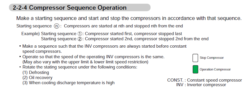
The controller creates a defined starting sequence for the available compressors. Compressors are then started and stopped according to their position in that sequence.
| Sequence position | Starting behaviour | Stopping behaviour |
|---|---|---|
| Starting sequence 1 | Compressor starts first. | Compressor stops last. |
| Starting sequence 2 | Compressor starts second. | Compressor stops second from the end. |
Key control rule: Inverter compressors are arranged so they start before constant-speed compressors.
2. Compressor operation
- The starting sequence determines the order in which compressors are brought into operation as system demand increases.
- When capacity is reduced, compressors are stopped in the reverse order of the starting sequence.
- The operating inverter compressors are controlled so that their speeds are the same.
- The inverter compressor speeds may still vary where upper- or lower-speed restrictions apply.
| Abbreviation | Meaning |
|---|---|
| INV | Inverter compressor |
| CONST. | Constant-speed compressor |
3. Starting sequence rotation
The compressor starting sequence is rotated under the following operating conditions:
1. Defrosting - the starting order may be changed when the system enters or completes defrost operation.
2. Oil recovery - the starting sequence is rotated as part of oil recovery control.
3. High cooling discharge temperature - sequence rotation can also occur when cooling discharge temperature is high.
This rotation changes which compressor is first in the sequence during the next operating cycle. The control strategy helps distribute compressor starts and operating time across the available compressors.
4. Compressor sequence control diagram
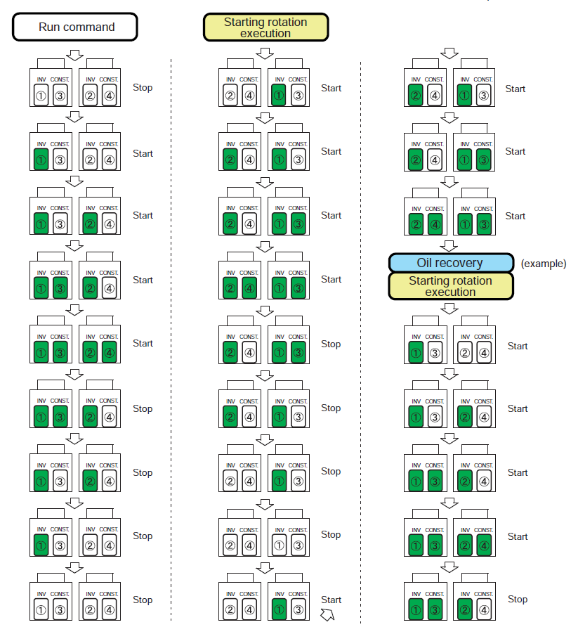
The following diagrams show an example of compressor start/stop sequencing and the change in starting order following sequence rotation.
5. Reading the sequence diagram
- Green compressor: operating compressor.
- White compressor: stopped compressor.
- As demand increases, additional compressors are started according to the active sequence.
- As demand decreases, compressors are stopped from the end of the active sequence.
- After a rotation event such as oil recovery, a different compressor can become the first compressor in the starting sequence.
Service note: A compressor not starting first on every cycle does not by itself indicate a fault. The system intentionally changes compressor sequence under the control conditions described above.
Important: This information explains the sequence-control principle shown in the referenced technical material. Always use the applicable service manual and model-specific diagnostic procedure when investigating an actual compressor or outdoor-unit fault.
GENERAL AIRSTAGE technical support reference - VRF compressor sequence control.