
VRF – VII Compressor Control
This article explains the compressor operating logic, capacity control, pressure control and inverter compressor speed control used by the VRF system described in the technical documentation.
Compressor operation is determined by the cooling or heating demand from indoor units on the same refrigerant circuit. Compressor capacity is then adjusted to suit the required refrigerant circulation and system operating pressures.
1. Compressor Operation / Stop Conditions
When a cooling requirement capacity or heating requirement capacity is received from an indoor unit on the same refrigerant circuit, the compressor operates.
When all indoor units have no cooling requirement capacity or heating requirement capacity, the compressor is normally stopped. However, compressor operation may continue or be controlled differently during specific system functions.
| Control / protective function | Effect on compressor operation |
| 3-minute restart prevention | Compressor operation follows the restart-protection control. |
| Icing protection | Compressor operation is controlled to protect the system. |
| Failure / protection control | Operation depends on the detected fault or protective condition. |
| Oil recovery | Compressor operation is managed by the oil recovery sequence. |
| Expansion valve initialisation | Compressor operation follows the initialisation sequence. |
| At protective operation / emergency stop | Compressor operation may be restricted or stopped. |
| Defrost operation | Compressor operation follows defrost control. |
| Peak cut stop operation | Compressor operation is limited or stopped as required. |
2. Compressor Capacity Control
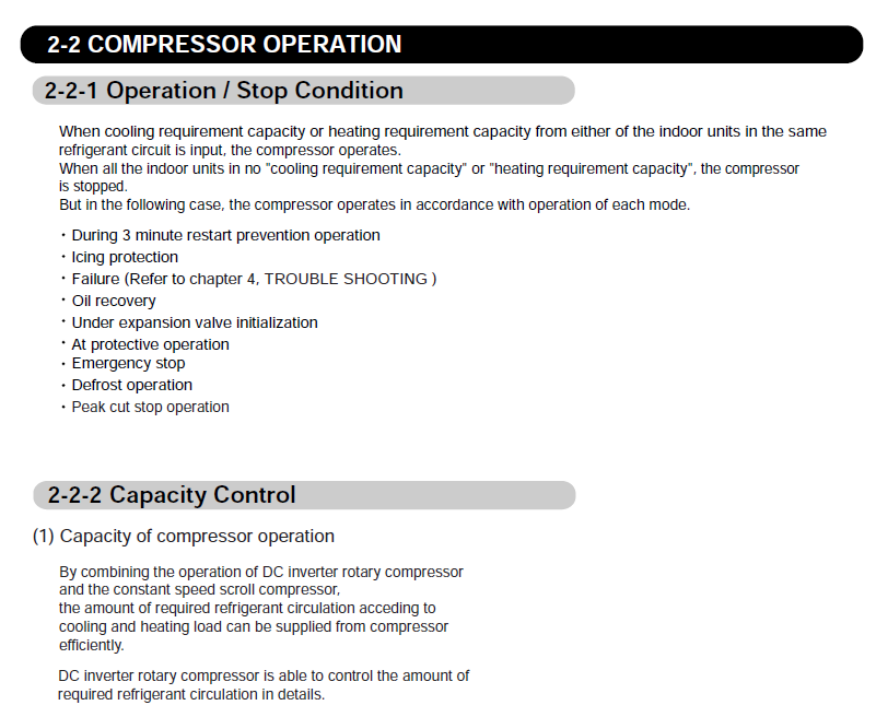
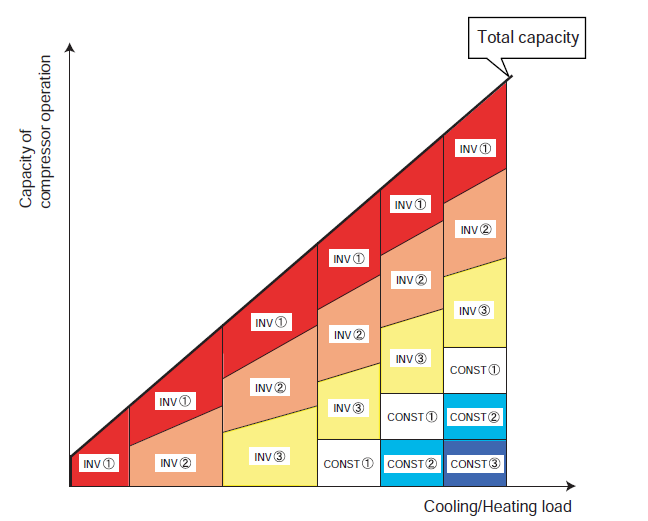
The system supplies the required refrigerant circulation for the cooling or heating load by combining compressor operation. The DC inverter rotary compressor provides fine control of the required refrigerant circulation.
As system demand increases, compressor capacity is increased progressively to meet the total required capacity. Depending on the outdoor unit configuration, this may involve inverter compressors and a constant-speed compressor.
3. Target Low-Pressure and High-Pressure Control
| Mode | Control method |
| Cooling | To maintain indoor-unit evaporation pressure at the required level, compressor capacity is controlled using the low-pressure sensor of the master outdoor unit. |
| Heating | To maintain indoor-unit condensation pressure at the required level, compressor capacity is controlled using the high-pressure sensor of the master outdoor unit. |
The target low-pressure and high-pressure temperature varies according to system capacity, compressor operating capacity, pipe length and capacity-shift switch settings.
4. DC Inverter Compressor Speed Range
| Condition | Compressor speed |
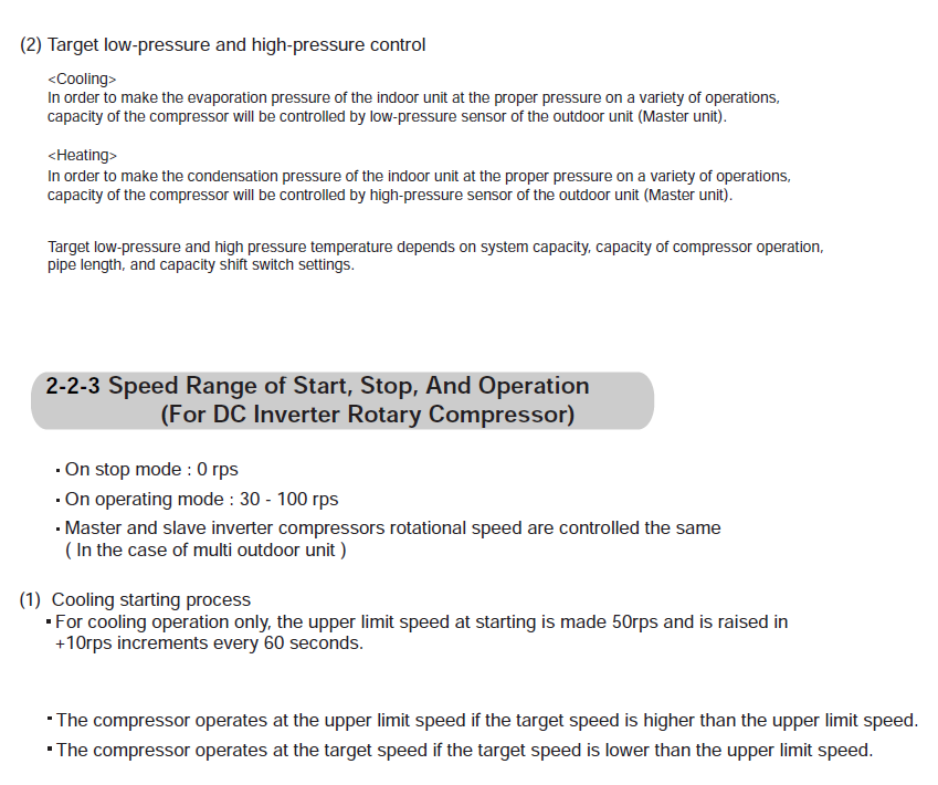
| Stop mode | 0 rps |
| Operating mode | 30–100 rps |
| Multi-outdoor system | Master and slave inverter compressor rotational speeds are controlled the same. |
Cooling starting process
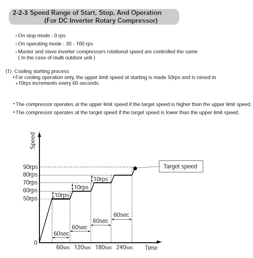
For cooling operation, the upper compressor speed limit at start-up is 50 rps. The upper limit then increases by 10 rps every 60 seconds.
- If the target speed is above the current upper limit, the compressor operates at the upper-limit speed.
- If the target speed is below the current upper limit, the compressor operates at the target speed.
5. Heating Starting Process
At the start of heating, compressor operation follows a controlled starting sequence. All compressors start to change the 4-way valve. Capacity control returns to normal control after the starting process is completed.
| Starting process | End condition |
| Process 1 | Ends when any applicable condition is satisfied: 7 minutes have elapsed; or 1 minute has elapsed and high pressure of all outdoor units is at least 2.50 MPa; or the compressor ratio of any outdoor unit is greater than 8. |
| Process 2 | Ends when any applicable condition is satisfied: 30 minutes have elapsed; or high pressure of all outdoor units is at least 2.63 MPa; or discharge superheat of all operating compressors is greater than 12°C. |
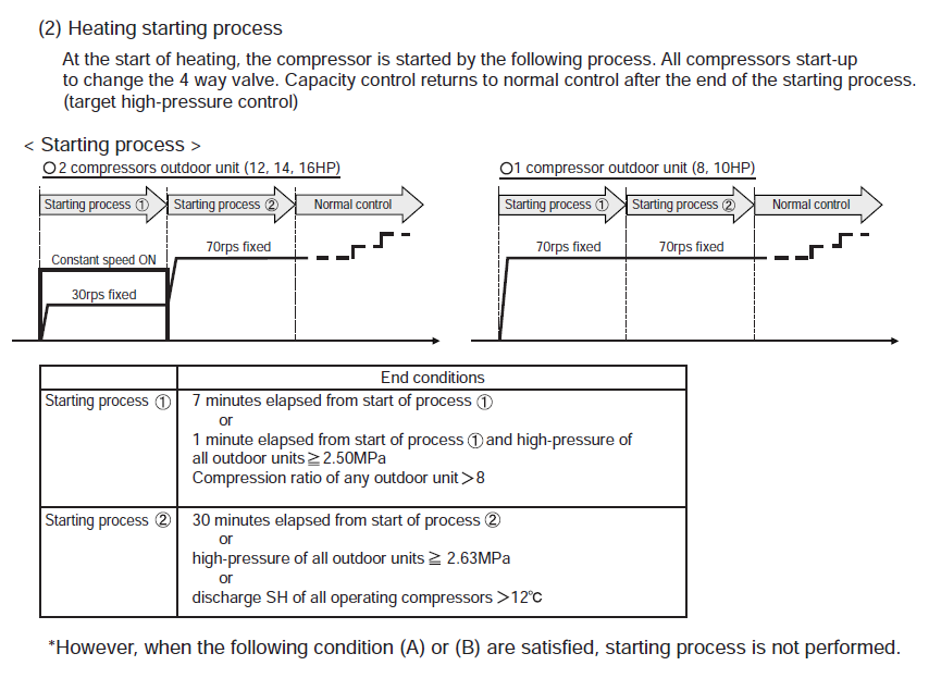
The documented starting process is bypassed when either of the following applies:
- Outside air temperature is greater than 20°C.
- The previous heating starting process stopped at the start of heating, including thermostat-OFF stop, within 30 minutes after heating stopped.
Under this condition, the inverter compressor of all outdoor units starts at 40 rps and normal target high-pressure control begins immediately.
6. High-Pressure Compressor Speed Limiting
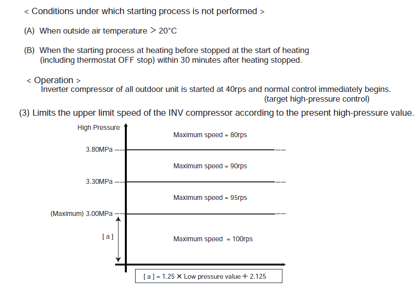
The inverter compressor upper-limit speed is restricted according to the current high-pressure value.
| High-pressure region | Maximum inverter compressor speed |
| 3.80 MPa and above | 80 rps |
| 3.30 MPa to below 3.80 MPa | 90 rps |
| [a] to below 3.30 MPa | 95 rps |
| Below [a] | 100 rps |
Technician Summary
- Indoor-unit demand determines whether compressor capacity is required.
- Cooling capacity is primarily regulated against low-pressure control at the master outdoor unit.
- Heating capacity is primarily regulated against high-pressure control at the master outdoor unit.
- Normal inverter compressor operating range is 30–100 rps.
- Cooling start-up limits compressor speed initially to 50 rps and increases the permitted limit in 10 rps steps every 60 seconds.
- During heating start-up, the system uses a defined pressure/time-based sequence before returning to normal control.
- High system pressure progressively reduces the permitted maximum inverter compressor speed.