
VRF – Test Run from the Outdoor PC Board
Purpose
This procedure explains how to initiate a cooling or heating test run directly from the outdoor unit printed circuit board using the push-button controls.
This procedure explains how to initiate a cooling or heating test run directly from the outdoor unit printed circuit board using the push-button controls.
Important
The outdoor PC board test-run function applies to the master outdoor unit only. All indoor units connected to that outdoor unit can be test-operated by this setting.
The outdoor PC board test-run function applies to the master outdoor unit only. All indoor units connected to that outdoor unit can be test-operated by this setting.
Outdoor PC Board Controls
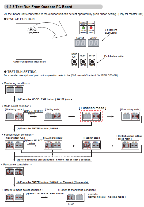
The test-run procedure uses the three push-button switches beside the 7-segment LED display:
| Switch | Function |
|---|---|
| SW107 | MODE / EXIT |
| SW108 | SELECT |
| SW109 | ENTER |
Starting a Test Run
- From the normal monitoring condition, press MODE / EXIT (SW107) once.
- Press SELECT (SW108) until Function mode is selected on the 7-segment display.
- Press ENTER (SW109) to enter the function selection.
- Use SELECT (SW108)to choose the required test-run function:
- Cooling test run
- Heating test run
- Test run stop
- With the required function displayed, press and hold ENTER (SW109) for at least 3 seconds.
- After the processing indication appears, press ENTER (SW109) once, or allow the display to time out after approximately 5 seconds.
- Press MODE / EXIT (SW107) to return to the normal monitoring display.
Stopping the Test Run
Repeat the function-selection process and choose Test run stop, then hold ENTER (SW109) for at least 3 seconds.
Reference
For detailed push-button operation and system design information, refer to the applicable D&T manual, Chapter 6 – System Design.
For detailed push-button operation and system design information, refer to the applicable D&T manual, Chapter 6 – System Design.
PC Board Test-Run Diagram
Use the diagram below as a visual guide to the switch locations and test-run sequence.
Technician check
Confirm you are working at the master outdoor unit, verify the required operating mode before starting the test, and return the system to the normal monitoring condition when testing is complete.
Confirm you are working at the master outdoor unit, verify the required operating mode before starting the test, and return the system to the normal monitoring condition when testing is complete.