
VRF - Changing a Master Unit to a Slave
1. Change the transmission wiring
If the original MASTER outdoor unit has failed, it must be removed electrically from the transmission network. The first remaining slave outdoor unit then becomes the new master.
Depending on the system configuration, the transmission wiring to the new master will need to be connected to:
- X1 / X2 for transmission to the indoor units; or
- Z1 / Z2 where the transmission continues to other refrigerant systems.

To operate with the failed master removed, electrically disconnect the failed master and reconnect the transmission so that Slave 1 becomes the new MASTER.

2. Set the outdoor unit addresses - DIP SW SET3-1 and SET3-2
Set the outdoor-unit address switches so each operating outdoor unit has the correct master/slave address.
| Outdoor unit role | Address | SET3-1 | SET3-2 |
|---|---|---|---|
| Master | 0 | OFF | OFF |
| Slave 1 | 1 | OFF | ON |
| Slave 2 | 2 | ON | OFF |

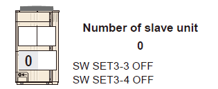
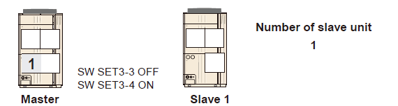
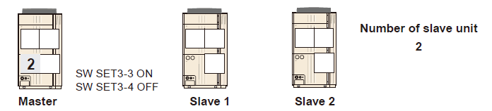
3. Set the number of slave units - DIP SW SET3-3 and SET3-4
If an outdoor unit is electrically disconnected from the refrigerant system, the new MASTER must be set for the number of slave outdoor units that remain connected.
| Operating outdoor units | Number of slaves | SET3-3 | SET3-4 |
|---|---|---|---|
| 1 - Master only | 0 | OFF | OFF |
| 2 - Master + Slave 1 | 1 | OFF | ON |
| 3 - Master + Slave 1 + Slave 2 | 2 | ON | OFF |
4. Set the number of outdoor units - DIP SW SET5-1 and SET5-2
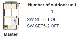
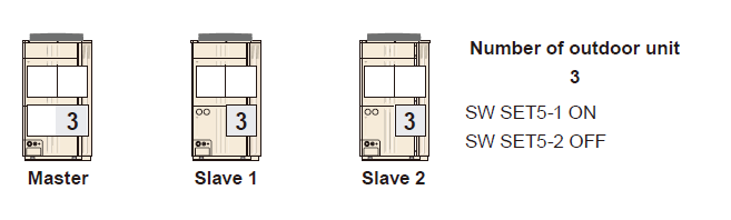
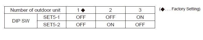
On the new MASTER, set DIP SW SET5-1 and SET5-2 to match the total number of outdoor units that are electrically connected and operating.
| Number of outdoor units | SET5-1 | SET5-2 |
|---|---|---|
| 1 | OFF | OFF |
| 2 | OFF | ON |
| 3 | ON | OFF |
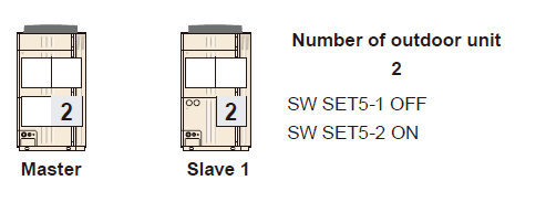
When the third outdoor unit is returned to service, restore the three-outdoor-unit configuration and reset the switches accordingly.
5. Final checks before operation
| 1 | Confirm the failed outdoor unit is electrically disconnected. |
| 2 | Confirm the transmission wiring now terminates at the correct new MASTER outdoor unit. |
| 3 | Confirm SET3-1 / SET3-2 address settings match the new master/slave arrangement. |
| 4 | Confirm SET3-3 / SET3-4 match the number of slave units connected to the new master. |
| 5 | Confirm SET5-1 / SET5-2 match the total number of operating outdoor units. |
| 6 | Close the service valves on the non-operational outdoor unit. |