
General Assist Technical Reference
AnyWair Ducted Controller (UTY-ANY1/2)
Controller wiring and connection points
The AnyWair ducted controller UTY-ANY1/2 wires together as shown below. Use the labelled connection points to identify the power, touch screen network cable, indoor unit link cable and zone motor connections.
1. Power and touch screen connections
The first side of the controller includes the power connection and the network connection to the touch screen.
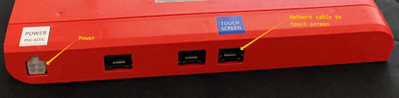
| Connection | Purpose |
|---|---|
| POWER | Controller power connection. |
| TOUCH SCREEN | Network cable connection to the AnyWair touch screen. |
2. Indoor unit and zone motor connections
The second side of the controller provides the link cable connection to the indoor unit and the RJ12 outputs for the zone motors.
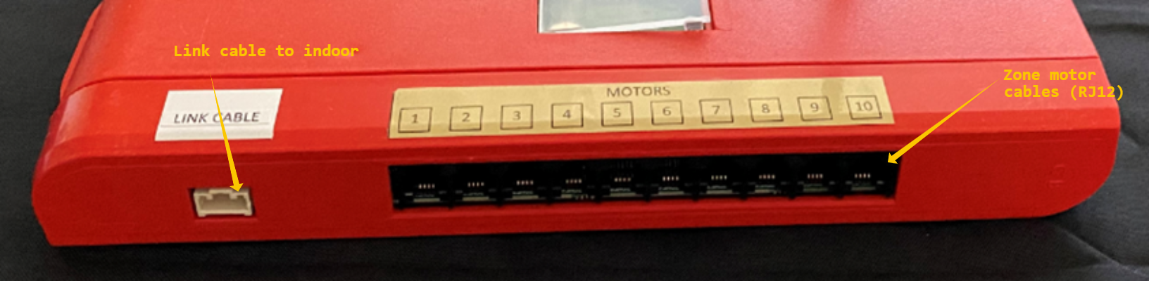
| Connection | Purpose |
|---|---|
| LINK CABLE | Link cable connection to the indoor unit. |
| MOTORS 1-10 | RJ12 connections for the zone motor cables. |
Important: Confirm each cable is connected to the correct labelled port before powering the controller. Do not force RJ-style connectors into the wrong socket.
Quick reference
| Port / Area | Connects to |
|---|---|
| POWER | Controller power supply |
| TOUCH SCREEN | Touch screen network cable |
| LINK CABLE | Indoor unit |
| MOTORS 1-10 | Zone motor cables (RJ12) |