
Does General Supply an Inverter Checker?
Available diagnostic tools and third-party inverter testing options
Overview
General does not sell or manufacture a dedicated inverter checker tool.
General does offer the UTY-ASSXZ1 diagnostic tool, which provides service and communication diagnostic functions on compatible General inverter systems.
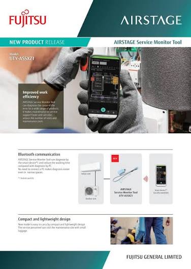
1. General Diagnostic Tool
2. Third-Party Inverter Checker Option
For direct inverter output testing, a third-party inverter phase check module may be used by suitably qualified technicians.
Inverter Output Test Procedure
| Indicator Result | Possible Interpretation |
|---|---|
| All phase LEDs illuminate evenly | Inverter output is likely operating normally. |
| One or more phase LEDs do not illuminate | The inverter board, driver circuit or output stage may be faulty. |
| LEDs illuminate briefly and then stop | Some inverter boards stop output when they do not detect a connected compressor. Brief and even illumination may still indicate that the output stage is functioning. |
Communication Data Flow Test
The checker may also be used to monitor communication between the indoor and outdoor control boards.
- Isolate the power supply before connecting the checker.
- Connect the checker probes to the applicable indoor-to-outdoor communication terminals in accordance with the checker manufacturer's instructions.
- Restore power and operate the system.
- Observe the communication LEDs.
| LED Activity | Possible Interpretation |
|---|---|
| Both LEDs flash alternately | Two-way communication is present. |
| Only one LED flashes | One control board may be transmitting without receiving a response. |
| Neither LED flashes | There may be no communication signal, an incorrect connection, a wiring fault or a control board issue. |
3. Safety Precautions
Inverter systems contain high DC voltages that may remain present after the power supply has been isolated. Testing must only be performed by appropriately licensed and qualified technicians.
Never connect or disconnect inverter checker leads while the system is energised.
Wait at least three minutes, or the period specified in the applicable service manual, before handling the inverter circuit.
Check the wiring diagram before connecting the tester. Do not assume terminal labels or voltages are the same across all models.
Do not use the inverter checker in wet, damp or otherwise unsafe environments.
The inverter checker must not remain permanently connected to the air conditioning system.
4. Tool Comparison
| Tool | Supplier | Primary Function | Notes |
|---|---|---|---|
| UTY-ASSXZ1 | General | System communication and service diagnostics | Official diagnostic tool for compatible General systems |
| EDC-IPCM 4040.0 | EDC International | Inverter output and communication data-flow testing | Third-party tool; follow the tool manufacturer's instructions |
| Other inverter testers | Various | Inverter output or communication testing | Confirm voltage range, connection method and system suitability before use |
5. Conclusion
General does not supply a dedicated inverter phase checker.
Service technicians may use:
- UTY-ASSXZ1 for compatible General system communication, operating data and service diagnostics.
- A suitable third-party inverter checker, such as the EDC-IPCM 4040.0, for direct inverter output and data-flow testing.
Always isolate the power supply before making connections, observe the required capacitor discharge period and follow the air conditioner and test equipment manufacturer's instructions.
Support
For technical assistance, contact Assist Technical Support:
Australia: 1300 364 484
New Zealand: +64 4 568 8761