
General Air Conditioning | Technical Service Advisory
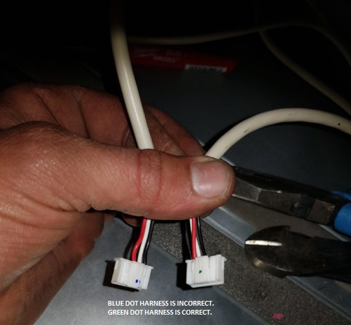
UTY-CDPXZC / UTY-CDPXZD Zone Module – Wire Harness Polarity Advisory
CN6 harness identification, polarity verification and corrective action
Critical warning: Do not use the Blue Dot harness. It may have reversed polarity and can cause communication failure, incorrect zone operation or module damage. Use only the Green Dot harness after confirming the CN6 pinout.
1. Overview
Some UTY-CDPXZC and UTY-CDPXZD Zone Modules may be supplied with a wire harness that has incorrect polarity at the CN6 connector. The issue is identified by the coloured dot marking on the harness plug.
| Affected model | Component | Connector |
|---|---|---|
| UTY-CDPXZC | Zone Module wire harness | CN6 |
| UTY-CDPXZD | Zone Module wire harness | CN6 |
2. Harness Identification
| Harness marking | Status | Action |
|---|---|---|
| Blue Dot | Incorrect | Do not install. Remove from service and arrange replacement. |
| Green Dot | Correct | Approved for connection to CN6 after checking the pinout below. |
Important: Do not rely only on the coloured dot. Confirm the actual wire sequence at the plug before connecting the harness to the Zone Module PCB.
3. Correct CN6 Pinout
When viewed in the connector numbering sequence, the correct wiring combination is:
| Pin | Wire colour | Requirement |
|---|---|---|
| 1 | Red | Must be fitted |
| 2 | White | Must be fitted |
| 3 | Black | Must be fitted |
| 4 | Not used | No wire |
| 5 | Not used | No wire |
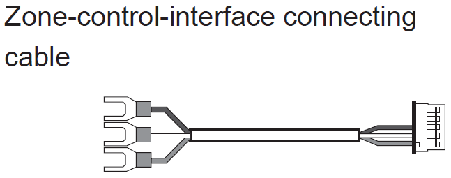
CN6 Connection Reference
1
RED 2
WHITE 3
BLACK 4
N/A 5
N/A
RED 2
WHITE 3
BLACK 4
N/A 5
N/A
4. Symptoms of Incorrect Harness Installation
- Zone controller does not operate correctly.
- Communication fault codes may be displayed.
- Zone Module LEDs may not illuminate or blink as expected.
- Zones may not open, close or respond to commands.
- Communication may be intermittent after power-up.
5. Corrective Action
| Step | Action |
|---|---|
| 1 | Isolate power to the indoor unit and Zone Module before disconnecting or reconnecting the harness. |
| 2 | Inspect the harness plug and identify the coloured dot marking. |
| 3 | Remove any Blue Dot harness from service. Do not reconnect it. |
| 4 | Confirm the Green Dot harness has Red on pin 1, White on pin 2 and Black on pin 3. |
| 5 | Reconnect the correct harness securely to CN6 on the Zone Module PCB. |
| 6 | Restore power and allow the controller and Zone Module to complete start-up. |
| 7 | Verify communication, LED status and zone operation. |
Do not attempt to repin the Blue Dot harness in the field unless specifically authorised. Replace it with the approved Green Dot harness to maintain traceability and avoid repeat failure.
6. Final Commissioning Checks
| Check | Expected result |
|---|---|
| Harness identification | Green Dot harness fitted |
| CN6 pinout | Pin 1 Red, Pin 2 White, Pin 3 Black |
| Connector seating | Plug fully inserted with no backed-out terminals |
| Zone Module LEDs | Normal indication and communication activity |
| Zone operation | All connected zones respond correctly |
| Fault history | No active communication fault remains |
7. Support
For replacement harnesses, configuration support or persistent zone communication faults, contact Assist Technical Support:
Australia: 1300 364 484
New Zealand: +64 4 568 8761
New Zealand: +64 4 568 8761