
General Assist Technical Reference
Thermistor Testing
Resistance testing and PCB thermistor-circuit voltage testing
For qualified service technicians working on General and Fujitsu General equipment
A temperature-sensing fault can be caused by the thermistor itself, its wiring or connector, or the PCB sensing circuit. Testing both resistance and operating voltage helps determine which component is responsible.
Electrical safety: Resistance testing must be completed with power isolated and the thermistor unplugged. Live DC-voltage testing exposes powered PCB components and must only be performed by qualified personnel using insulated probes and suitable PPE.
1. Preparation
| 1 | Identify the thermistor. Confirm whether it is the room, indoor heat-exchanger, outdoor heat-exchanger, outdoor-air, discharge or compressor-temperature sensor. |
| 2 | Measure the actual temperature. Use a reliable contact thermometer and allow the sensor and reference thermometer to stabilise at the same location. |
| 3 | Inspect the circuit. Check the sensor tip, cable, connector, terminal tension, corrosion and signs of moisture or physical damage. |
| 4 | Select the correct chart. Different thermistor types use different resistance curves. Do not compare a discharge thermistor with a room-temperature thermistor chart. |
The measured temperature must be taken at the sensor location. Room temperature is not a valid reference for a pipe, discharge or compressor thermistor unless the sensor has been removed and allowed to stabilise at room temperature.
2. Thermistor resistance test
| 1 | Isolate power and wait the time specified in the model service manual before accessing the PCB. |
| 2 | Unplug the thermistor connector from the PCB. Do not measure resistance while it remains connected to the board. |
| 3 | Set the multimeter to resistance (Ω) and select a range capable of reading the expected kilohm value. |
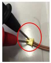
| 4 | Turn the connector over and carefully contact the two exposed metal strips or terminals with the meter probes. |
| 5 | If the probes are too large, use thin insulated test leads, a fine wire or a straightened paper clip as a temporary probe extension. Prevent the two terminals from shorting together. |
| 6 | Compare the resistance with the correct thermistor chart at the measured temperature. |
Resistance-test interpretation
| Reading | Likely finding |
|---|---|
| Matches chart reasonably at actual temperature | Thermistor resistance is likely serviceable; continue with wiring and PCB-voltage checks. |
| Open circuit / OL | Broken thermistor element, lead or connector. |
| Near zero resistance | Shorted thermistor or wiring. |
| Significantly different from chart | Thermistor out of calibration, wrong chart, inaccurate temperature reference or wiring problem. |
| Reading jumps when cable is moved | Intermittent lead or connector fault. |
Most thermistors used in this reference are negative-temperature-coefficient sensors: resistance falls as temperature rises. A reading that moves in the opposite direction suggests the wrong chart or a sensor fault.
3. PCB thermistor-circuit voltage test
This is a live-board test. Avoid slipping probes, shorting adjacent tracks or contacting mains and inverter circuits. Use back-probing pins or fine insulated probes.
| 1 | Reconnect the thermistor to the PCB and restore power in accordance with the service procedure. |
| 2 | Set the multimeter to DC volts. |
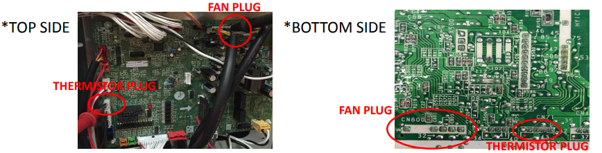
| 3 | Connect the black meter lead to a verified PCB DC neutral. The source document uses the black wire in the indoor fan-motor connector as the reference on the illustrated board. |
| 4 | Back-probe the thermistor connector from the top of the board, or carefully measure at the corresponding solder points on the underside. |
| 5 | Measure both thermistor pins relative to DC neutral. The reference circuit shows one side near 5 V DC and the signal side varying with temperature. |
| 6 | Compare the variable signal voltage with the correct voltage chart for the thermistor type and actual temperature. |
Reference-ground caution: Only use the fan-connector black wire when the applicable wiring diagram confirms it is the correct DC neutral for that PCB. Connector colours and board architecture can differ between models.
Voltage-test interpretation
| Finding | Next action |
|---|---|
| Thermistor resistance is correct and signal voltage matches chart | Sensor circuit is likely normal. Investigate fault history, connector security, software logic and operating conditions. |
| Thermistor resistance is wrong | Replace the thermistor or repair its wiring. |
| 5 V reference is missing or materially incorrect | Check supply rails, connector and PCB. Confirm other thermistor circuits before condemning the board. |
| 5 V reference is present but signal voltage is wrong with a known-good thermistor | Inspect wiring and PCB input circuit; PCB replacement may be required. |
| Voltage changes when connector or cable is moved | Repair loose terminals, damaged wiring or cracked solder joints. |
4. Thermistor-versus-PCB decision guide
| Resistance test | Voltage test | Likely action |
|---|---|---|
| Fails chart | Not required initially | Replace thermistor or repair its harness. |
| Passes chart | Fails chart or reference supply | Check connector, PCB supply and sensing circuit; replace PCB only after confirming wiring and reference ground. |
| Passes chart | Passes chart | Thermistor circuit is likely serviceable; continue diagnosis elsewhere. |
| Intermittent | Intermittent | Inspect harness, terminals and PCB solder joints under movement and temperature change. |
Do not replace a PCB solely because one voltage differs from a generic chart. Confirm the correct thermistor type, actual sensor temperature, DC reference point, wiring integrity and model-specific service data.
5. Thermistor reading charts
Page 3 of the uploaded reference contains separate resistance and voltage tables for the room, indoor heat-exchanger, outdoor heat-exchanger, outdoor-temperature, discharge and compressor-temperature thermistors.
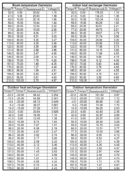
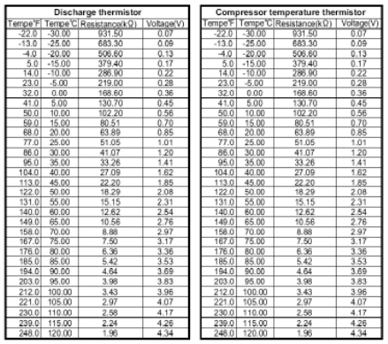
Quick reference at 20°C
| Thermistor type | Approx. resistance | Approx. signal voltage |
|---|---|---|
| Room temperature | 12.54 kΩ | 2.22 V |
| Indoor heat exchanger | 62.91 kΩ | 2.21 V |
| Outdoor heat exchanger | 6.09 kΩ | 2.19 V |
| Outdoor temperature | 12.51 kΩ | 3.77 V |
| Discharge / compressor temperature | 63.89 kΩ | 0.85 V |
The quick-reference figures above are taken from the supplied chart and are useful only when the thermistor is actually at approximately 20°C. Use the full table for other temperatures.
6. Original illustrated procedure
7. Information required for technical escalation
- Complete indoor and outdoor model numbers
- Thermistor name and PCB connector number
- Actual measured temperature at the sensor
- Measured thermistor resistance
- Measured 5 V reference and signal voltage
- DC-neutral reference point used
- Fault code and whether it is current or intermittent
- Photos of the connector, wiring and PCB test points
- Whether readings change when the harness is moved
Based on the uploaded General Assist “How to Test Temperature Thermistors” reference. Resistance and voltage curves are thermistor-specific and may differ between models. Always confirm the applicable wiring diagram and service data before replacing a sensor or PCB.