General Assist Technical Reference
V-II Series Outdoor Wiring Diagram Reference
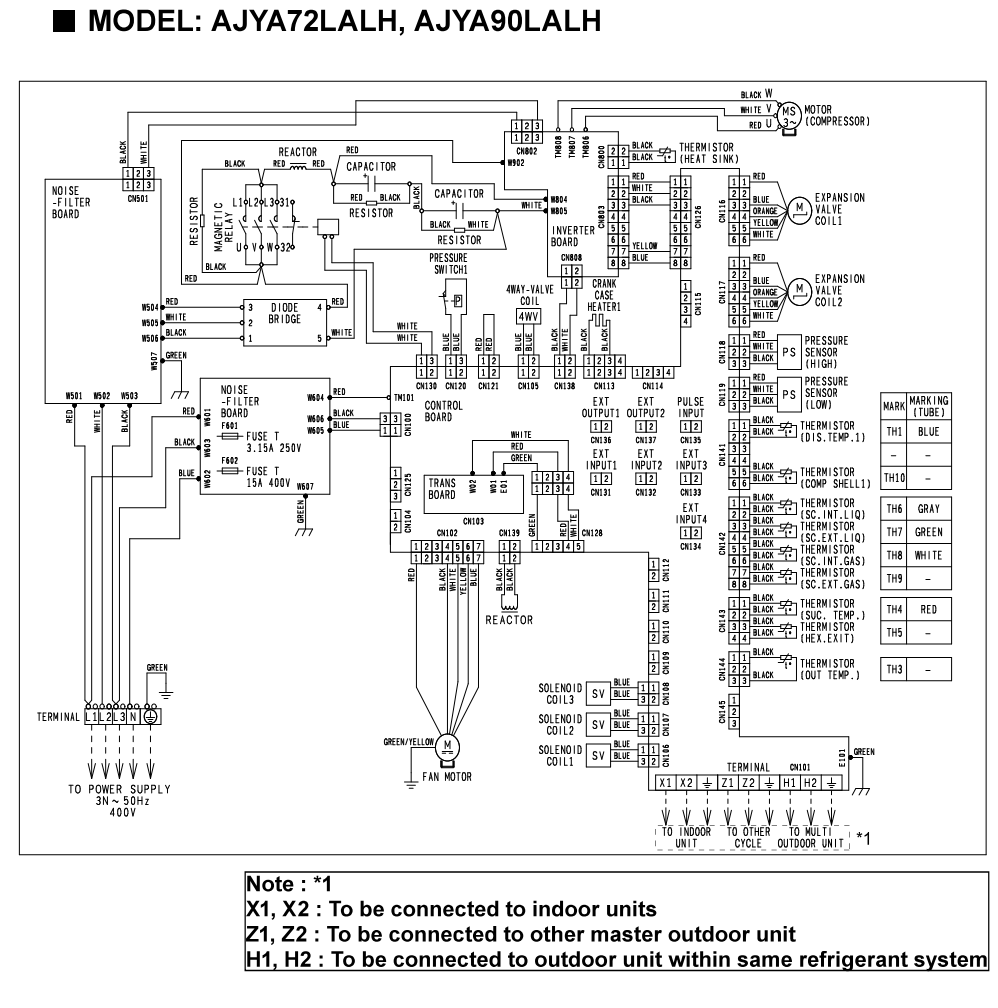
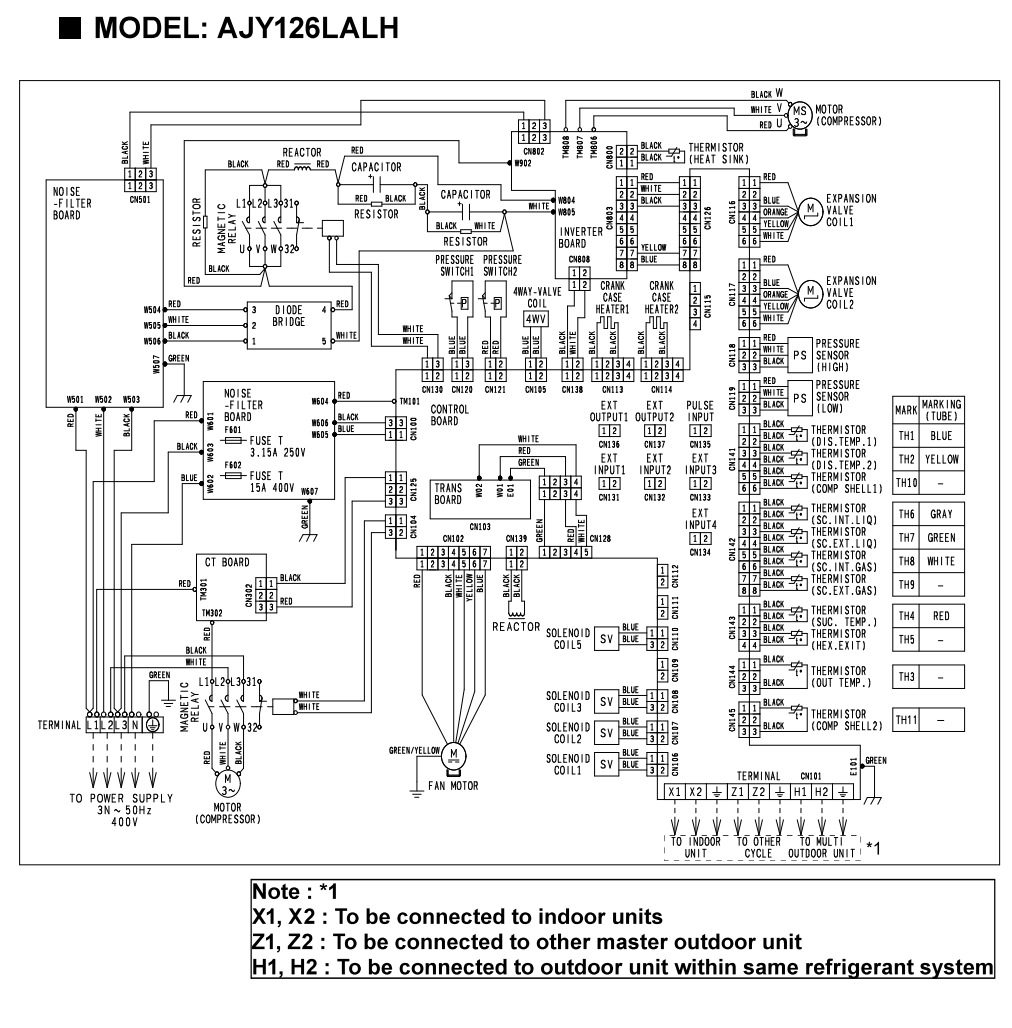
AJYA72LALH / AJYA90LALH / AJY126LALH
Electrical interconnections, major components, thermistor identification and transmission terminals
This solution provides a schematic reference for the V-II Series outdoor units. It is intended to support installation verification, fault diagnosis, PCB replacement and service work by showing the electrical relationship between the power circuit, control boards, inverter section, compressor, fan motor, expansion valves, sensors and transmission terminals.
High-voltage warning: These units contain 400 V three-phase supply, high DC-bus voltage and stored capacitor energy. Testing must only be completed by qualified personnel using correctly rated instruments and PPE. Confirm discharge time before touching inverter or capacitor circuits.
1. Diagram and model mapping
| PDF page | Model | Compressor arrangement | Key difference |
|---|---|---|---|
| 1 | AJYA72LALH / AJYA90LALH | Single inverter compressor | Includes inverter board and one compressor motor connection |
| 2 | AJY126LALH | Inverter compressor plus additional compressor control | Includes CT board and additional compressor-related wiring |
Model suffix matters: Use the complete model number. Do not apply this diagram to V Series, V-III, VR-II, VR-III or other outdoor units with similar capacity numbers.
2. Major electrical components
| Component | Function | Service focus |
|---|---|---|
| Noise-filter board | Filters incoming supply noise and protects the downstream power circuit | Check fuses, supply continuity, heat damage and loose terminals |
| Diode bridge | Rectifies the AC supply into DC for the inverter circuit | Check for short circuit, open circuit and abnormal DC-bus voltage |
| Reactor and capacitors | Smooth and stabilise the DC-bus circuit | Inspect for swelling, heat damage, loose connections and DC-bus collapse under load |
| Inverter board | Drives the compressor motor at variable frequency | Check DC input, U/V/W output balance, IPM condition and compressor current |
| Control board | Processes sensor inputs and controls valves, relays, fan and communication | Check LEDs, connector seating, address switches and output commands |
| CT board | Monitors compressor current on the AJY126LALH arrangement | Confirm current-transformer wiring and board connections |
| Fan motor | Controls outdoor airflow | Check motor winding, feedback, connector and commanded output |
| Expansion-valve coils | Modulate refrigerant flow through EEV coils 1 and 2 | Check coil resistance, plug position and valve movement |
| Pressure sensors and switches | Monitor and protect high- and low-pressure operation | Compare sensor output with gauge pressure and verify switch continuity |
| Case and crankcase heaters | Prevent refrigerant migration and oil dilution | Check supply, continuity and relay output |
| Solenoid coils 1-3 | Switch refrigerant circuit paths | Check coil resistance, output voltage and correct connector location |
3. Power and transmission terminals
| Terminal | Connection | Important note |
|---|---|---|
| L1 / L2 / L3 / N / Earth | 400 V three-phase power supply | Verify phase supply, neutral where fitted, earth continuity and phase balance |
| X1 / X2 | Indoor-unit transmission network | Observe transmission cable requirements and avoid connection to mains voltage |
| Z1 / Z2 | Connection to another master outdoor unit | Used in applicable multi-outdoor arrangements only |
| H1 / H2 | Connection to another outdoor unit within the same refrigerant system | Confirm master/slave arrangement and refrigerant-system addressing |
Never megger the transmission terminals or connected control PCBs. Isolate and disconnect sensitive electronic circuits before insulation-resistance testing.
4. Thermistor and tube-marking reference
| Thermistor | Typical function shown | Tube marking |
|---|---|---|
| TH1 | Heat-sink thermistor | Blue |
| TH2 | Compressor temperature 1 | Yellow |
| TH3 | Outdoor-air thermistor | No tube colour shown |
| TH4 | Heat-exchanger temperature 1 | Blue |
| TH5 | Heat-exchanger temperature 2 | Gray |
| TH6 | Compressor temperature 2 | No tube colour shown |
| TH7 | Heat-exchanger temperature 3 | Gray |
| TH8 | Heat-exchanger gas temperature | Green |
| TH9 | Heat-exchanger gas temperature | White |
| TH10 | Heat-sink thermistor 2 | No tube colour shown |
| TH11 | Subcool heat-exchanger thermistor 2 | No tube colour shown |
| TH12 | Subcool heat-exchanger liquid temperature | Red |
| TH13 | Subcool heat-exchanger gas temperature | No tube colour shown |
Do not identify a sensor by wire colour alone. Confirm the PCB connector number, thermistor reference and physical tube location before replacement.
5. Wiring-diagram troubleshooting workflow
| 1 | Confirm the exact model and diagram page. Use page 1 for AJYA72LALH / AJYA90LALH and page 2 for AJY126LALH. |
| 2 | Identify the failed function. Separate the fault into power supply, compressor drive, fan, valve, sensor, pressure protection or communication. |
| 3 | Trace from the load back to the board. Check the component, harness, connector, PCB output and upstream supply in that order. |
| 4 | Compare command with actual operation. Confirm whether the control board is commanding the output and whether voltage/current reaches the component. |
| 5 | Check sensors against actual conditions. Compare thermistor resistance with temperature and pressure-sensor output with gauge pressure. |
| 6 | Inspect all connectors before replacing a PCB. Look for loose pins, overheated plugs, corrosion, damaged harnesses and incorrect connector positions. |
6. PCB replacement checklist
| Check | Done |
|---|---|
| Old PCB part number recorded | ☐ |
| All DIP switches and rotary switches photographed | ☐ |
| Replacement PCB settings matched exactly | ☐ |
| Every connector returned to the correct terminal | ☐ |
| Refrigerant-system and outdoor-unit addresses confirmed | ☐ |
| Capacity check and commissioning completed | ☐ |
| Operation tested in heating and cooling where conditions allow | ☐ |
Escalation information: Provide the complete model and serial number, fault code, LED status, measured supply voltages, DC-bus voltage, compressor current, thermistor readings, pressure-sensor readings and photos of the PCB connectors and switch settings.
Based on the supplied V-II Series outdoor wiring diagrams for AJYA72LALH, AJYA90LALH and AJY126LALH. This article is a simplified service reference and does not replace the complete service manual, wiring diagram or electrical safety procedures.