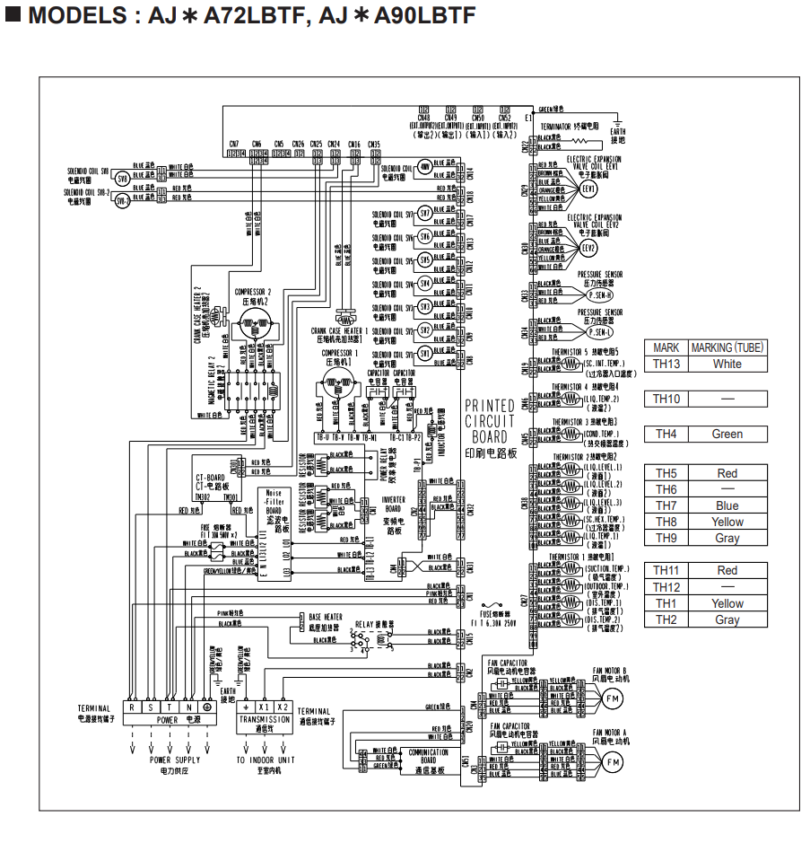
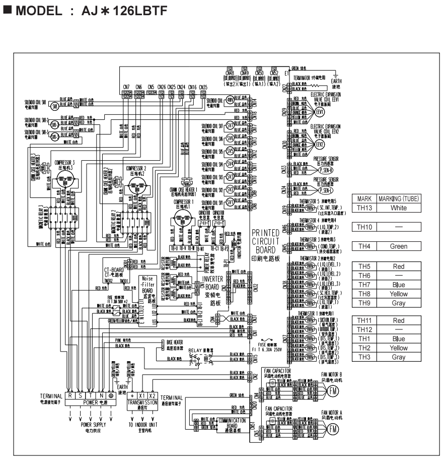
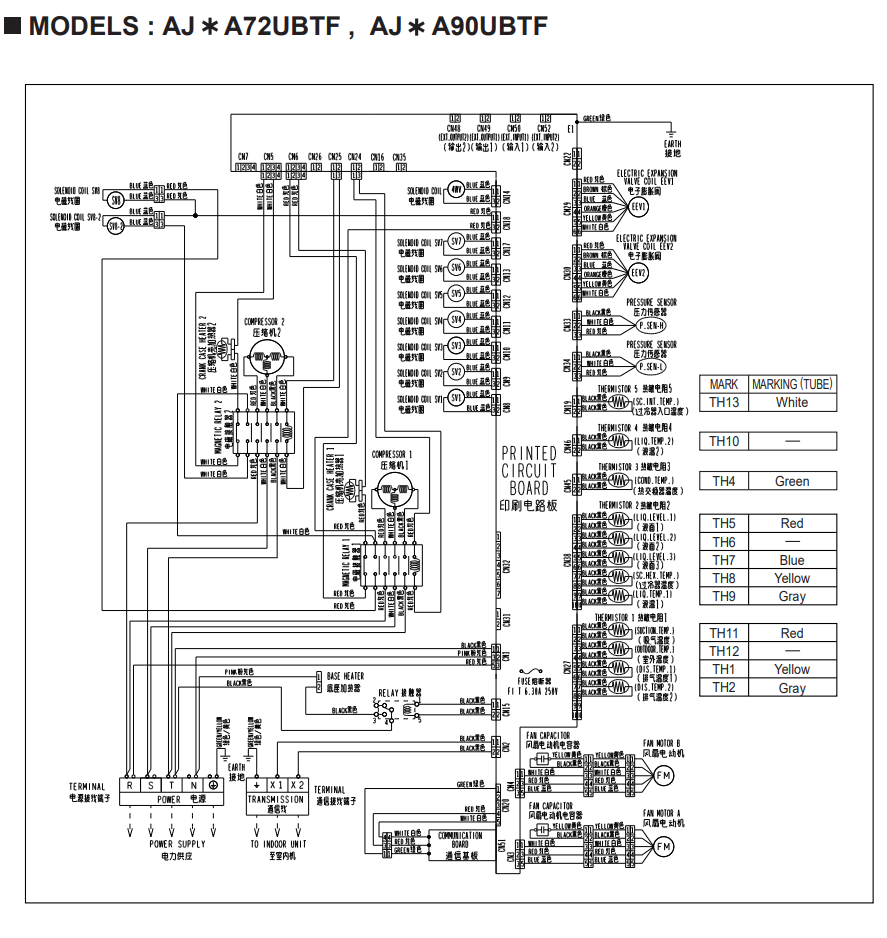
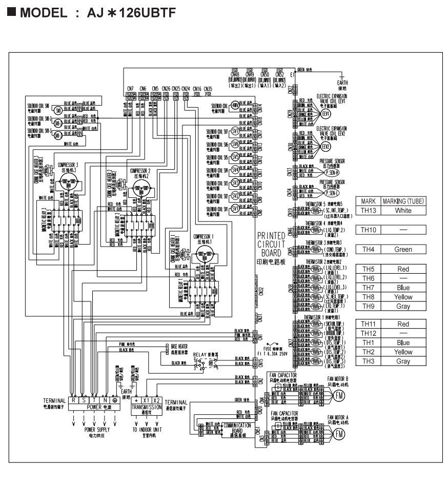
Freshdesk-safe version: Paste this code into the Freshdesk HTML/source editor. Attach the original four-page wiring-diagram PDF to the article so technicians can enlarge the schematics.
General Assist Technical Reference
V Series Outdoor-Unit Wiring Diagrams
Electrical interconnection and component reference
Applicable AJ*A72LBTF, AJ*A90LBTF, AJ*126LBTF, AJ*A72UBTF, AJ*A90UBTF and AJ*126UBTF outdoor units
This solution provides a structured reference to the V Series outdoor-unit wiring schematics. The diagrams identify power-supply terminals, transmission wiring, printed circuit boards, inverter circuits, compressors, fan motors, electronic expansion valves, pressure devices and thermistors.
Danger - hazardous voltage: These outdoor units contain mains voltage and high-voltage DC inverter circuits. Testing must only be completed by suitably qualified personnel using correctly rated instruments, PPE and isolation procedures. Stored DC voltage may remain after the supply is isolated.
1. Model and diagram page guide
| PDF page | Applicable models | Configuration shown |
|---|---|---|
| 1 | AJ*A72LBTF / AJ*A90LBTF | L-type outdoor wiring with two compressors and two outdoor fan motors |
| 2 | AJ*126LBTF | Higher-capacity L-type wiring with three compressors and two outdoor fan motors |
| 3 | AJ*A72UBTF / AJ*A90UBTF | U-type outdoor wiring with two compressors and two outdoor fan motors |
| 4 | AJ*126UBTF | Higher-capacity U-type wiring with three compressors and two outdoor fan motors |
Wildcard model notation: The asterisk shown in the source diagram represents a market or product-code character. Confirm the full rating-label model before using a diagram.
2. Major circuit sections
| Circuit section | Function and checks |
|---|---|
| Power-supply terminal | Incoming outdoor-unit power and protective earth. Confirm supply arrangement, phase voltage, phase balance, terminal condition and earth continuity against the rating label and installation manual. |
| Transmission terminal X1 / X2 | Communication connection to the indoor-unit network. Check continuity, polarity requirements where applicable, cable type, shielding and separation from mains wiring. |
| Printed circuit board | Central outdoor control board receiving sensor and protection inputs and commanding compressors, valves and fans. |
| Inverter board / CT board | Controls inverter-driven compressor operation and monitors current. Inspect connectors, fuses, reactor/noise-filter path and high-voltage DC circuit before condemning a compressor. |
| Compressors | Two compressors are shown on the 72/90 diagrams and three on the 126 diagrams. Confirm winding resistance, insulation resistance, running current and drive output using the model-specific service procedure. |
| Fan capacitors and fan motors | Two outdoor fan circuits are shown. Check motor connectors, winding condition, fan freedom, capacitor condition where fitted and PCB output. |
| Electronic expansion valves | Multiple EEV coils connect to the main PCB. Match each plug to its labelled valve and confirm coil resistance and connector seating before replacement. |
| Pressure and protection devices | Includes pressure sensors/switches, compressor protection and other safety inputs. An open circuit or incorrect input can prevent or stop compressor operation. |
| Crankcase / oil heaters and relay circuits | Heater and relay circuits support compressor reliability. Verify the correct output and heater continuity when oil-temperature or startup issues are suspected. |
3. Thermistor identification and tube markings
The schematics identify thermistor harnesses as TH1 through TH13. Several sensors use coloured tube markings to distinguish otherwise similar connectors and harnesses.
| Thermistor mark | Tube marking shown |
|---|---|
| TH13 | White |
| TH10 | No coloured tube marking shown |
| TH4 | Green |
| TH5 | Red |
| TH6 | No coloured tube marking shown |
| TH7 | Blue |
| TH8 | Yellow |
| TH9 | Gray |
| TH11 | Red |
| TH12 | No coloured tube marking shown |
| TH1 | Yellow on the L-type 72/90 diagram; blue on the U-type 72/90 and 126 diagrams |
| TH2 | Gray on the 72/90 diagrams; yellow on the 126UBTF diagram |
| TH3 | Gray on the 126LBTF and 126UBTF diagrams |
Do not identify a thermistor by connector shape alone. Confirm the TH number, PCB socket label, harness route and coloured tube marking. The tube-colour allocation is not identical across every model diagram.
4. Wiring-diagram troubleshooting workflow
| 1 | Confirm the exact model. Read the complete outdoor-unit model from the rating label and select the matching PDF page. |
| 2 | Identify the failed function. Determine whether the issue relates to power, communication, compressor operation, fan operation, valve control, pressure protection or temperature sensing. |
| 3 | Trace the circuit from load to control. Follow the motor, valve, sensor or relay wiring back to the PCB connector rather than testing isolated components without context. |
| 4 | Check connectors and harnesses. Inspect for loose pins, incorrect plugs, damaged insulation, corrosion, overheated terminals and harnesses trapped against sharp metal. |
| 5 | Test the component using model-specific data. Use the service manual for expected resistance, voltage, current or waveform. The wiring diagram identifies connections but does not provide every test value. |
| 6 | Confirm operation after repair. Restore covers, complete commissioning checks and verify that the repaired circuit operates without fault codes or abnormal current draw. |
5. Before replacing a PCB
| Check | Done |
|---|---|
| Correct diagram selected for full outdoor model | ☐ |
| Incoming power, phase condition and earth verified | ☐ |
| Fuses, reactors, noise filters and power connections checked | ☐ |
| Connected compressor, fan, EEV, heater and relay loads tested | ☐ |
| Thermistors and pressure inputs checked against service data | ☐ |
| All harness plugs photographed and labelled before removal | ☐ |
| DIP switches, rotary switches and jumper positions recorded | ☐ |
| Replacement PCB part number and supersession confirmed | ☐ |
PCB replacement: Transfer all switch and jumper settings exactly. Complete any model-specific addressing, initialisation and capacity-check procedure required by the service manual before returning the system to operation.
6. Information required for technical escalation
Provide the following with the support request:
- Complete outdoor model and serial number
- Applicable wiring-diagram page
- Fault code and outdoor LED display
- Supply voltages and phase-to-phase readings
- Transmission voltage or communication test results
- Relevant sensor resistance and temperature
- Compressor and fan current readings
- PCB part numbers and details of any recent replacement
- Clear photographs of the PCB, plugs and affected wiring
Based on the four-page V Series outdoor-unit wiring-diagram extract covering AJ*A72LBTF, AJ*A90LBTF, AJ*126LBTF, AJ*A72UBTF, AJ*A90UBTF and AJ*126UBTF. This article is a navigation and troubleshooting aid and does not replace the complete installation or service manual.