General Assist Technical Reference
DTGY & DTGYZ1 Plug
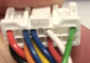
Touch Panel Controller connector wire location
In some instances, individual wires can become dislodged from the connector used on the DTGY / DTGYZ1 Touch Panel Controller. This reference is intended to assist with returning the wires to the correct connector positions.
Important: Isolate power before handling the connector or attempting to reseat any terminal. Do not force a terminal into the housing. Confirm that each terminal is fully locked into position before reconnecting the plug.
Connector wire arrangement
With the connector viewed in the same orientation as the original reference photo, the visible wire sequence is:
| Position | Wire colour |
|---|---|
| 1 | Red |
| 2 | Orange |
| 3 | Blue |
| 4 | Yellow |
| 5 | Blue |
| 6 | Red |
| 7 | White |
| 8 | Green |
Orientation is critical. The sequence above is based on viewing the connector from the wire-entry side in the same orientation as the source photograph. If the connector is rotated or viewed from the terminal face, the apparent left-to-right order will be reversed.
If a wire has pulled out
| 1 | Isolate power to the Touch Panel Controller and associated equipment. |
| 2 | Inspect the displaced terminal for damage, distortion or a broken locking tab. |
| 3 | Return the terminal to the correct cavity using the wire arrangement above. |
| 4 | Gently pull back on the wire to confirm the terminal has locked into the connector housing. |
| 5 | Reconnect the plug, restore power and confirm normal Touch Panel Controller operation. |
Do not rely on wire colour alone if the harness has previously been repaired or modified. If more than one terminal has been removed and the original arrangement cannot be confirmed, compare the harness with an undisturbed unit or the applicable wiring documentation before energising the controller.