
General Assist Technical Reference
Wall-Mounted Split System Defrost Flow Sequence
Defrost initiation, control actions and termination conditions
Technical overview for heating operation on applicable wall-mounted split systems
The defrost cycle is controlled automatically using compressor operating time and outdoor heat exchanger temperature. The system prevents defrost during the first 10 minutes after the compressor starts, then applies different criteria for the first, subsequent and integrating defrost cycles.
1. Defrost control overview
During heating operation, frost may form on the outdoor heat exchanger. The system continuously monitors compressor runtime and heat exchanger temperature to determine when defrosting is required.
Heating operation start: The compressor begins operating. Defrost is inhibited for the first 10 minutes after compressor startup.
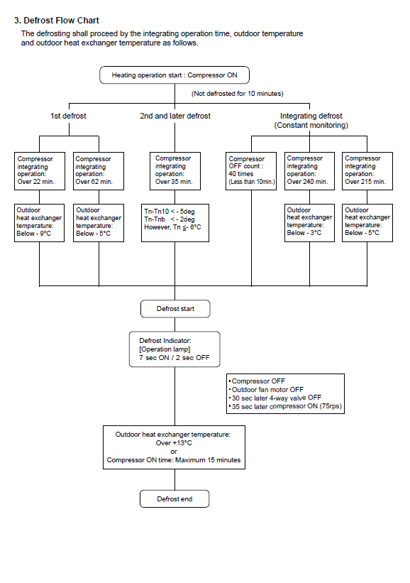
Defrost flow chart showing initiation and termination conditions.
2. Defrost initiation criteria
| Defrost type | Compressor operating condition | Temperature condition |
|---|---|---|
| First defrost | Over 22 minutes | Outdoor heat exchanger temperature below -9 °C |
| Over 62 minutes | Outdoor heat exchanger temperature below -5 °C | |
| Second and later defrosts | Over 35 minutes | Tn - Tn10 < -5 °C and Tn - Tnb < -2 °C, while Tn is below -6 °C |
| Integrating defrost Constant monitoring | 40 compressor OFF counts of less than 10 minutes each | No separate temperature threshold shown in the flow chart |
| Over 240 minutes | Outdoor heat exchanger temperature below -3 °C | |
| Over 215 minutes | Outdoor heat exchanger temperature below -5 °C |
Temperature reference terms:
Tn is the current outdoor heat exchanger temperature used by the control logic.
Tn10 and Tnb are internal reference values used by the controller to assess the rate and pattern of heat exchanger temperature change.
Tn is the current outdoor heat exchanger temperature used by the control logic.
Tn10 and Tnb are internal reference values used by the controller to assess the rate and pattern of heat exchanger temperature change.
3. Control sequence during defrost
When any applicable initiation condition is satisfied, the system begins the defrost sequence.
| 1 | The operation indicator flashes for 7 seconds ON and 2 seconds OFF. |
| 2 | The compressor switches OFF. |
| 3 | The outdoor fan motor switches OFF. |
| 4 | After 30 seconds, the 4-way valve switches OFF. |
| 5 | After 35 seconds, the compressor restarts at 75 rps. |
Normal operation: During defrost, the indoor fan may stop and the unit may temporarily stop producing warm air. Water or steam may also be visible at the outdoor unit as frost melts. These conditions are normally part of the defrost process.
4. Defrost termination conditions
Defrost ends when either of the following conditions is reached:
| Termination condition | Threshold |
|---|---|
| Outdoor heat exchanger temperature | Above +13 °C |
| Compressor operating time during defrost | Maximum 15 minutes |
Once defrost ends, the system changes back to normal heating operation and the operation indicator returns to its standard display pattern.
5. Summary
- Defrost is disabled for the first 10 minutes after heating operation starts.
- The first, subsequent and integrating defrost cycles use different runtime and temperature criteria.
- The compressor, outdoor fan and 4-way valve are controlled in sequence during defrost.
- Defrost ends when the outdoor heat exchanger rises above +13 °C or after a maximum of 15 minutes.