1. Overview
The UTY-RVNYN wired remote controller includes internal DIP switches used to configure memory backup and dual remote controller operation modes. These settings determine how the controller retains data and how it communicates when connected in a dual configuration.
2. Switch Position
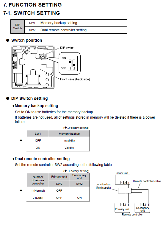
The DIP switches (SW1 and SW2) are located on the back side of the front case of the controller, as shown below.
| Switch | Function |
|---|---|
| SW1 | Memory backup setting |
| SW2 | Dual remote controller setting |
3. DIP Switch Setting Descriptions
3.1 Memory Backup Setting (SW1)
This setting enables the use of batteries for memory retention.
If backup batteries are not installed, all stored settings will be erased in the event of a power failure.
| SW1 Position | Function | Description |
|---|---|---|
| OFF (Factory setting) | Invalid | Settings are erased if power is lost. |
| ON | Valid | Memory settings are retained using battery backup. |
Note: Always install fresh batteries when enabling the memory backup function to prevent data loss.
3.2 Dual Remote Controller Setting (SW2)
This switch defines whether the controller operates as a Primary or Secondary unit in a dual remote setup.
| Configuration | Controller Type | SW2 Position |
|---|---|---|
| Single Controller (Normal) | Primary only | OFF |
| Dual Controller (Two units) | Primary | OFF |
| Dual Controller (Two units) | Secondary | ON |
4. Wiring Reference
When using dual controllers, connect both controllers to the indoor unit using a junction box (field supply) and polar 3-core cable.
Maintain correct polarity between all terminals (1-2-3).
Ensure cable length and type comply with wiring specifications.
Do not connect more than two controllers to one indoor unit.
Example Connection Diagram: