GENERAL Assist Technical Reference
Outside Air Handling Unit (OAU) Commissioning Procedure
Commissioning a 100% fresh-air unit connected to a VRF refrigerant system
Airflow, refrigeration performance, valve operation, drainage, noise and documentation checks
The outdoor unit commissioning criteria do not change solely because an OAU is connected to the refrigerant circuit. However, the OAU requires additional checks for airflow, static pressure, superheat, subcooling, discharge-air temperature, solenoid-valve operation, drainage, noise and vibration.
Qualified service personnel only: Commissioning must be completed by technicians trained in VRF systems, refrigerant pressure-temperature relationships, electrical safety and Service Tool operation. Confirm the applicable model documentation before applying the values in this article.
1. Pre-commissioning checks
| 1 | Confirm the refrigerant circuit, OAU model and OAU address. |
| 2 | Confirm refrigerant piping, insulation, electrical connections, thermistor connections and drain installation are complete. |
| 3 | Confirm filters, ductwork, grilles and dampers are installed and open to their intended commissioning positions. |
| 4 | Connect the Service Tool and confirm the relevant TH, EEV, SV, HPS and LPS values can be monitored. |
| 5 | Confirm the design airflow and external static pressure requirements are available before testing. |
2. Airflow volume and static pressure
Measure velocity at each outlet and calculate airflow using the appropriate formula.
| Outlet type | Formula | Measurements |
|---|
| Rectangular | Q = W × H × v | Width (W), height (H) and air velocity (v) |
| Circular | Q = πR² × v | Radius (R) and air velocity (v)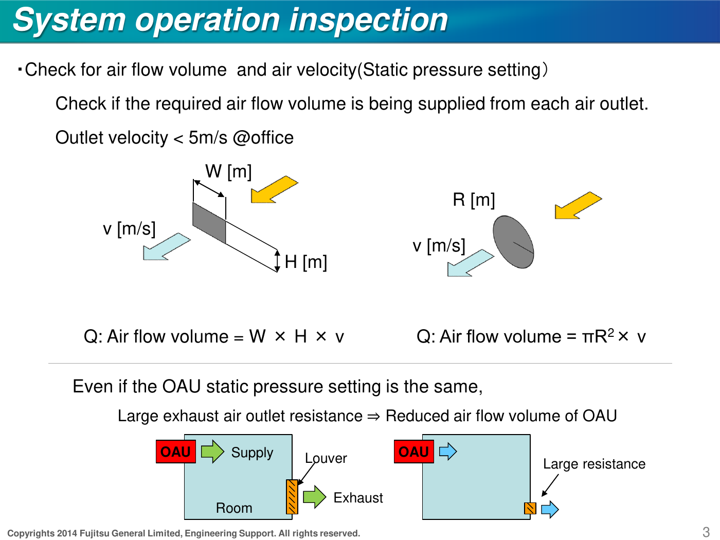 |
Target: Confirm total airflow matches the design requirement. For office applications, outlet velocity should be below 5 m/s. High outlet or duct resistance can reduce airflow even when the OAU static-pressure setting has not changed.
3. Cooling test-run operation
Reference condition in source document: Outdoor air 27°C, set temperature 14°C, V-II outdoor unit.
| Check | Calculation / value | Acceptance criterion |
|---|
| OAU superheat | ΔTshe = TH24 − TH22 | 2°C ≤ ΔTshe ≤ 10°C |
| Discharge-air temperature | TH25 | Set temperature − 5°C or higher |
| OAU EEV | Pulse position | 45–1400 pulses; 45 pulses is closed |
Values outside the expected range may indicate incorrect refrigerant charge, poor refrigerant flow caused by piping layout, a TH21/TH22/TH24/TH25 sensor issue, or incorrect external static-pressure settings.
Outdoor-unit refrigeration checks during cooling
| Outdoor-unit subcooling | 5°C ≤ ΔTsc (TH6 − TH7) ≤ 20°C |
| EEV3 | EEV3 ≤ 400 pulses |
| Discharge pressure | 2.5 MPa ≤ HPS ≤ 3.3 MPa |
| Suction pressure | 0.7 MPa ≤ LPS ≤ 1.2 MPa |
| Discharge temperature | TH1 ≤ 100°C |
| Discharge superheat | ΔTshd = TH1 − saturated vapour temperature at HPS; ΔTshd > 10°C |
| SV3 | Open |
4. Heating test-run operation
Reference condition in source document: Outdoor air 7°C, set temperature 28°C, V-II outdoor unit.
| Check | Calculation / value | Acceptance criterion |
|---|
| OAU subcooling | ΔTsc = saturated liquid temperature at HPS − TH22 | 4°C ≤ ΔTsc ≤ 50°C |
| Discharge-air temperature | TH25 | Warm air must be discharging |
| OAU EEV | Pulse position | 45–1400 pulses |
Outdoor-unit refrigeration checks during heating
| Discharge pressure | 2.5 MPa ≤ HPS ≤ 3.3 MPa |
| Suction pressure | 0.3 MPa ≤ LPS ≤ 1.2 MPa |
| Discharge temperature | TH1 ≤ 100°C |
| Discharge superheat | TH1 − saturated vapour temperature at HPS > 10°C |
| Outdoor-unit refrigerant superheat | 2°C ≤ ΔTshe (TH4 − TH5) ≤ 5°C |
5. Solenoid valve SV21 verification
During heating, SV21 should open when the OAU is thermostat-off while at least one other indoor unit on the same refrigerant circuit remains in heating operation.
| System condition | Expected result |
|---|
| Another indoor unit is heating and the OAU is thermostat-off | SV21 opens; TH21 ≈ TH22 ≈ TH25; OAU EEV closes to 45 pulses |
| All indoor units stop or become thermostat-off | SV21 closes |
6. Drainage, noise and vibration
| Water check | Inspect the OAU during cooling. No water should drip or fall from the indoor unit. |
| Noise check | Confirm there is no hitting, rattling or abnormal vibration noise from the OAU. |
| Drain check | Confirm the drain line is correctly graded, trapped where required and discharging freely without leakage. |
7. Commissioning documentation
Record the refrigerant circuit name, OAU address, operating mode, pressures, temperatures, calculated superheat/subcooling, EEV pulse positions, airflow and inspection results.
| Record | Cooling | Heating |
|---|
| HPS / LPS | Record | Record |
| TH1 / TH21 / TH22 / TH24 / TH25 | As applicable | As applicable |
| Superheat / subcooling | Record calculated values | Record calculated values |
| EEV pulse position | Record | Record |
| Airflow / velocity | Record total m³/h and m/s | Record total m³/h and m/s |
| Water / noise / vibration | Confirm acceptable | Confirm acceptable |
8. R410A pressure-temperature reference
The source document provides an R410A reference example where an HPS pressure of approximately 2.58 MPa corresponds to a saturated liquid temperature of approximately 44°C. Use the applicable refrigerant pressure-temperature data and the actual measured pressure when calculating subcooling.
Important: The presentation was issued in 2014 and uses a V-II/R410A example. Thermistor numbers, valve references and acceptable values may vary by outdoor-unit series. Always cross-check the current service manual for the installed equipment.
9. Completion criteria
- Design airflow achieved and outlet velocity acceptable.
- Cooling superheat and heating subcooling within the applicable range.
- Discharge-air temperature responds correctly in both modes.
- EEV and SV21 operation confirmed.
- No water leakage, abnormal noise or excessive vibration.
- All commissioning values recorded and retained with the project documentation.
Technical reference based on Fujitsu General Engineering Support, “Commissioning for OAU”, dated 15 April 2014.
