
VRF Compressor Replacement Procedure - S Series, V Series and V-II
This article provides a service procedure for replacing compressors on larger VRF systems and outlines the additional work required where an acid-contaminated or burn-out condition is identified.
Recommended Scope on Larger VRF Systems
- Where a major compressor failure has occurred, it is recommended that all compressors are replaced.
- Replace the oil separator.
- Replace the suction accumulator.
- If a compressor burn-out has occurred, flush the system and follow the acid-removal procedure below.
Applicable Products
- Product: VRF Outdoor Units
- Series: S Series, V Series and V-II Series
- Subject: Correct compressor replacement procedure
Safety: This procedure is intended for qualified refrigeration technicians. Isolate and tag electrical power before starting work, recover refrigerant using approved equipment, and follow all applicable electrical, refrigerant and pressure-system safety requirements.
Compressor Replacement Procedure
- Determine the type of compressor failure.
Establish whether the failure is mechanical, electrical, refrigerant-related, or a compressor burn-out. - Isolate and tag the electrical supply.
- Recover and weigh the refrigerant.
Record the amount of refrigerant removed from the system.- Compare the recovered quantity with the refrigerant charge recorded on the outdoor unit.
- If the recovered quantity is lower than expected, pressure test and leak check the system.
- Do not continue until any confirmed leak has been repaired.
- If the pressure test confirms there is no leak, continue to the next step.
- Disconnect the compressor electrically from the system.
- Perform an oil acidity test.
If no acid is present, proceed to the non-acid procedure below. If acid is present, follow the burn-out procedure.
If Acid Is Present - Burn-Out Procedure
- Flush the system.
- Install a replaceable-core burn-out drier in the suction line after the three-way service valve.
- Install a hand isolation valve after the suction-line drier to allow easy replacement or removal of the drier.
- Ensure there is a Schrader valve between the two isolation points.
- Use nitrogen while brazing.

If No Acid Is Present
Install a bi-flow drier in the liquid line after the three-way service valve.
- Install a hand isolation valve after the drier.
- Ensure there is a Schrader valve between the two isolation points.
- Use nitrogen while brazing.
Compressor Removal and Installation
- Remove the failed compressor.
Keep nitrogen flowing through the pipework while brazing to prevent internal oxidation. - Install the replacement compressor using nitrogen while brazing.
- Pressure test the system with nitrogen.
- Evacuate the system to 500 microns or lower.
- Recharge the system.
Weigh in the correct refrigerant quantity using refrigerant scales and charge refrigerant in the liquid state. - Leak check all new joints.
- Reconnect the compressor electrically.
- Remove the danger tag and restore power.
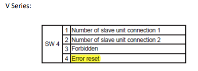
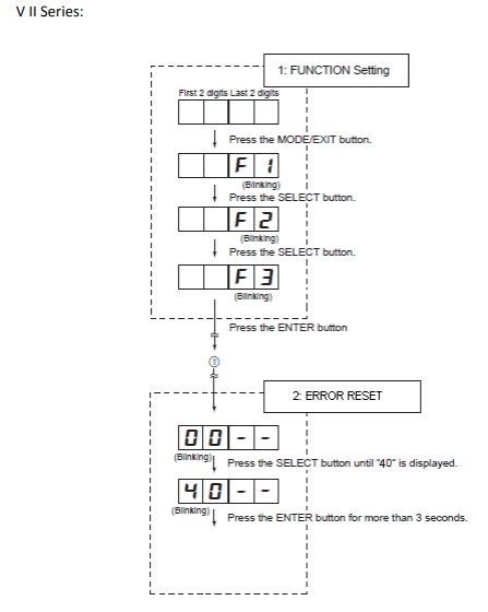
- Reset the fault / error if required.
Test Operation
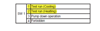
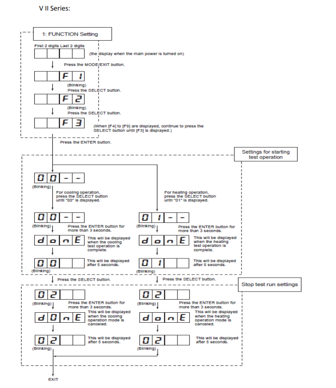
- Run the system in TEST MODE and confirm correct operation.
For S Series and V Series systems, use the applicable outdoor-unit TEST MODE procedure shown below.
Post-Repair Checks
- Confirm compressor current and operating condition are normal.
- Confirm all replacement joints are leak free.
- Confirm the correct refrigerant charge has been weighed into the system.
- Confirm cooling and heating operation where applicable.
- Confirm no abnormal compressor noise or vibration is present.
- If a burn-out drier was installed, monitor the system and replace or remove the core as required by the applicable service procedure.
Burn-out reminder: Where acid contamination is confirmed, simply replacing the failed compressor is not sufficient. The contaminated system must be cleaned and managed to prevent damage to the replacement compressor.