System Signal Test
Indoor and outdoor unit communication diagnostic procedure
Overview
The System Signal Test verifies serial communication between the indoor and outdoor units in a split or multi-system configuration. It confirms whether both units are correctly exchanging control signals through the communication line.
Testing can be completed from either the indoor or outdoor terminal block, allowing technicians to isolate faults involving interconnecting wiring or the indoor and outdoor control boards.
Safety warning - live DC and AC circuits
Testing is performed with power ON. Use insulated probes, wear appropriate personal protective equipment, and do not allow the probes to short adjacent terminals.
Testing conditions
- Confirm the power supply is active and both units are energised.
- Use a digital multimeter set to DC voltage.
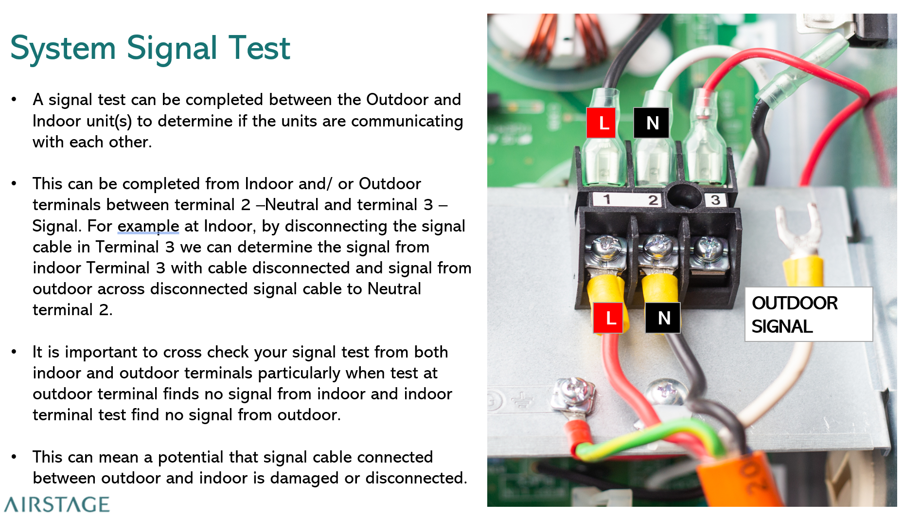
- Identify the terminals on both the indoor and outdoor terminal blocks:
| Terminal | Function |
|---|---|
| 1 | L - Live |
| 2 | N - Neutral |
| 3 | Signal / serial communication |
Test procedure
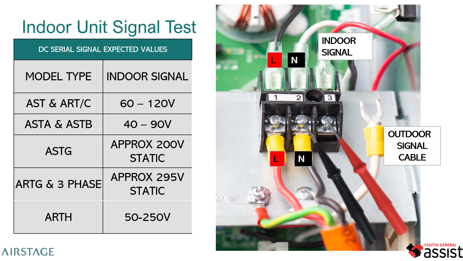
1. Indoor unit test
- Locate the indoor unit terminal block.
- Disconnect Terminal 3, the signal wire leading to the outdoor unit.
- Measure DC voltage between Terminal 2 (Neutral) and the disconnected signal wire.
- This reading represents the outdoor unit signal returning to the indoor connection.
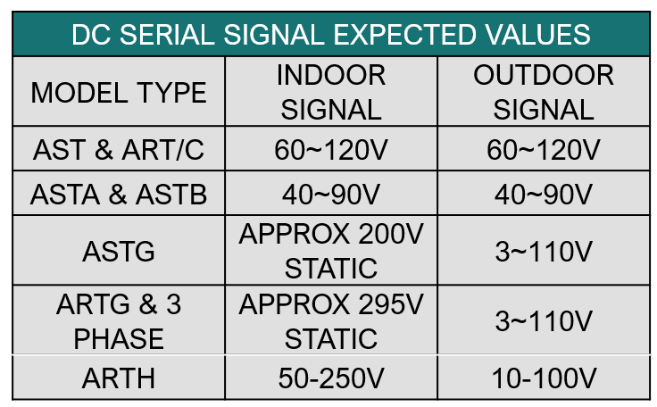
Indoor test reference: Match the indoor model family to the expected DC voltage below.
| Indoor model type | Expected signal |
|---|---|
| AST and ART/C | 60-120 V DC |
| ASTA and ASTB | 40-90 V DC |
| ASTG | Approximately 200 V DC - static |
| ARTG and three-phase systems | Approximately 295 V DC - static |
| ARTH | 50-250 V DC |
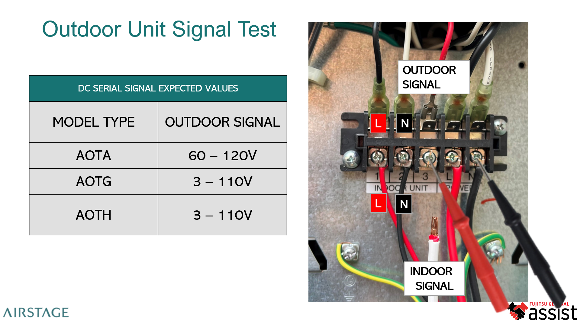
2. Outdoor unit test
- Locate the outdoor unit terminal block.
- Disconnect Terminal 3, the signal cable connected to the indoor unit.
- Measure DC voltage between Terminal 2 (Neutral) and the disconnected signal wire.
- This reading represents the indoor unit signal reaching the outdoor connection.
| Outdoor model type | Expected signal |
|---|---|
| AOTA | 60-120 V DC |
| AOTG | 3-110 V DC |
| AOTH | 3-110 V DC |
3. Cross-check the communication path
- A normal signal at one unit but no corresponding signal at the other end indicates a possible damaged, disconnected, or open-circuit interconnecting signal cable.
- No signal from either unit indicates a possible indoor or outdoor control PCB fault.
Diagnosis and interpretation
| Observation | Likely diagnosis | Recommended action |
|---|---|---|
| Signal voltage is within range at both units | Communication is operating normally | No communication fault detected |
| Signal is present at one end only | Broken, loose, or disconnected interconnecting cable | Inspect, test, and repair the wiring |
| No signal from either unit | Possible indoor or outdoor control PCB fault | Confirm the failed board before replacement |
| Signal is unstable or fluctuates abnormally | Poor termination, damaged wiring, or electrical noise | Check terminations, cable condition, routing, and earthing |
Technical notes
- Terminal 3 carries a DC serial data signal used for control communication between the indoor and outdoor units.
- The multimeter displays an average of the pulsed DC signal, so the reading may fluctuate during operation.
- Always use Terminal 2 (Neutral) as the reference point for these measurements.
- For multi-split systems, test each indoor-to-outdoor communication path individually.
Reference diagrams